J
jennychanAug 13, 2025
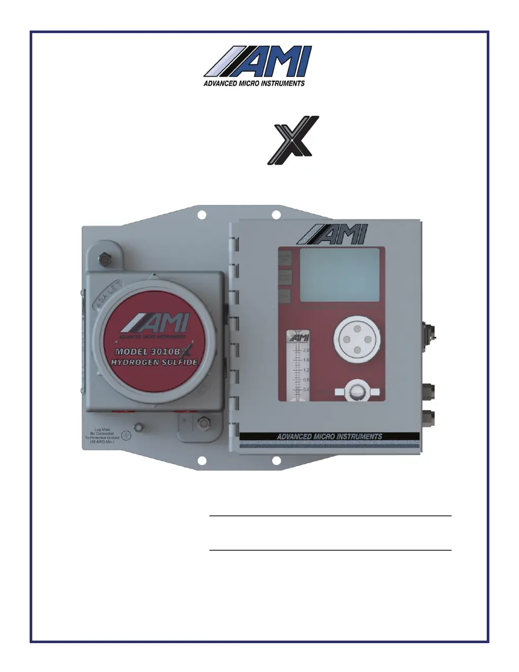
How to fix AMI 3010B Measuring Instruments if the analyzer does not power up?
- MMatthew JohnsonAug 13, 2025
If your AMI Measuring Instruments analyzer is not powering up, ensure the power is properly connected and that you are using the correct version for your power supply. Also, verify that the power supply voltage is between 10V and 24VDC or 100V to 240VAC. Make sure the power plug is fully seated in its socket and that no whiskers or wires are shorting.