Rev. 2 13
Installation
Connecting the Transmitters to the Sensors
2.4.1 Connecting a Capacitance Sensor
The sensor may be connected directly to the BNC connector on the
instrument rear panel if the length of the coaxial cable is 15 feet or less. If
the sensor is greater than 15 feet from the instrument, an external
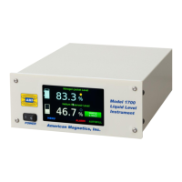
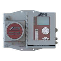
oscillator/transmitter unit must be used. Refer to figures “Model 1700
Instrument using internal oscillator/transmitter” on page 2 and“Model
1700 Instrument using external oscillator/transmitter” on page 3 as
appropriate.
If the transmitter is connected to the sensor with a length of coaxial cable,
the a 15 ft standard length cable, with part number of EH2362, is
available from AMI. Contact the factory for details. Speak to an AMI Sales
Engineer before using cables longer than 15 feet.
Note
Regarding the coaxial cable is used to connect the capacitance level sensor to
the instrument or oscillator/transmitter, in order to maintain system
performance and accuracy, the cable must be Trompeter TCC-75-2 and
should not be longer than 15 feet [4.57 m]. If a longer length section of
coaxial cable is necessary, please discuss with an Authorized AMI Technical
Representative.
Note
If an oscillator/transmitter is used, the length of coaxial cable between the
oscillator/transmitter and the instrument may be up to 500 feet in length.
Caution
Moisture or contaminants in any of the BNC coaxial connectors can short out
the sensor and cause an erroneous readings or transmitter failure. A pack of
non-conductive electrical connection lubricant (ECL or “Dielectric Tune-up
Grease”) has been included with the liquid level sensor packaging to reduce
the possibility of this occurring.
To connect the coaxial cable to the BNC connector on the capacitance level
sensor:
1. Apply a small amount of ECL to any of the BNC connectors that
may be exposed to moisture.
2. Mate the ECL-coated connectors then remove any excess ECL from
the outside of the connector.
3. Cover the ECL-coated connections with a short section of heat-
shrink tubing, also included, for added moisture protection.