38 Rev. 2
Calibration
Capacitance-Based Level Calibration
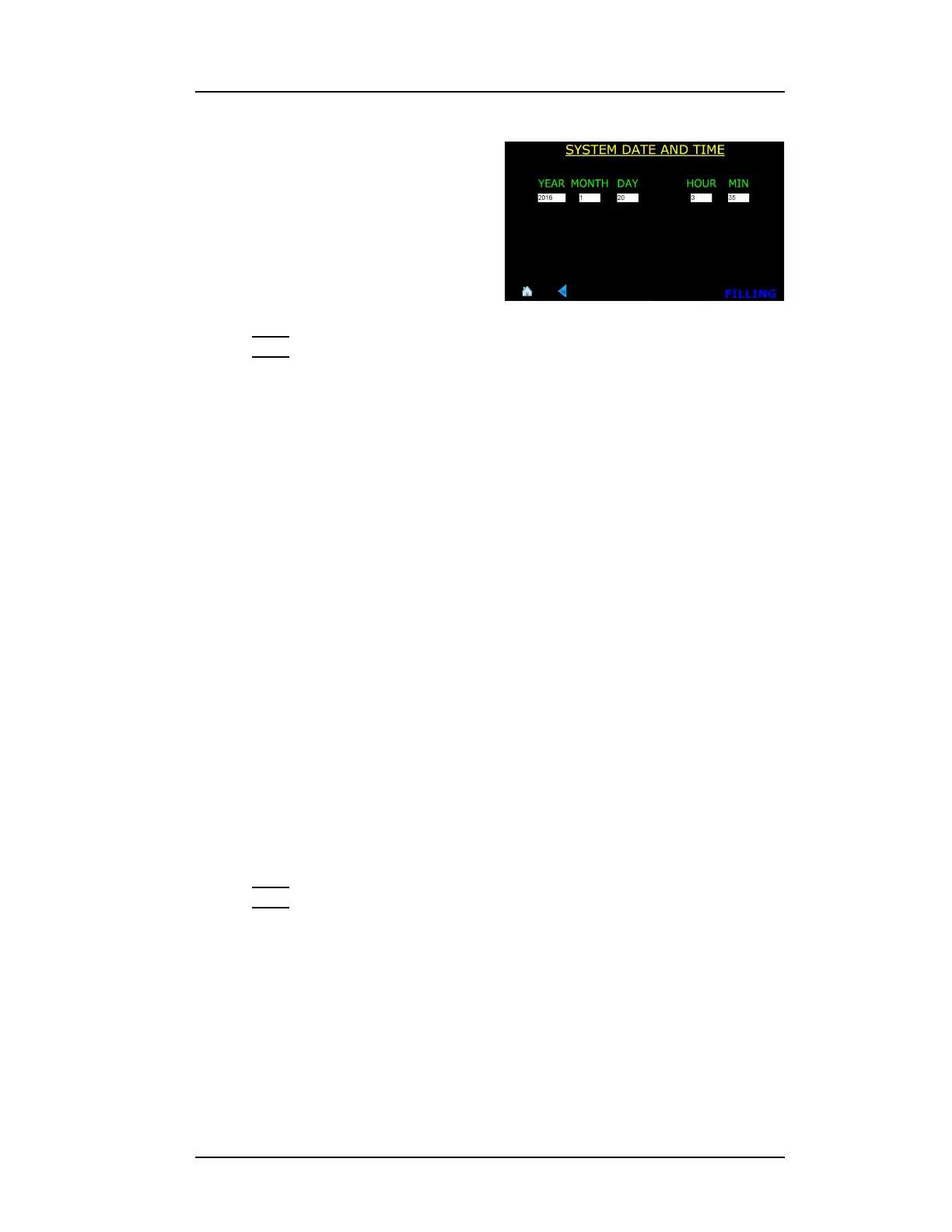
4. Edit the YEAR, MONTH, DAY,
HOUR, and MIN fields as
necessary. Touching in a field
will launch the keyboard on the
screen. Edit the information in
the field as necessary and
choose Enter to enter the data
in the field and close the pop up
keyboard.
Note
The clock is set to GMT at the factory and is battery backed. There is
no provision in the instrument for automatic Daylight Savings Time
correction.
5. Choose SAVE in the footer after all the fields have been edited as
necessary.
4.2 Capacitance-based Level Calibration
4.2.1 Understanding the Sensor Active Length
American Magnetics, Inc. fabricates the liquid level sensor with two vent
holes; a lower vent hole in the side wall near the bottom which is typically
the minimum liquid level calibration point and the upper vent hole in the
sensor side typically near the top of the sensor. The liquid level location
approximately 2.5 cm (1 in) below the upper vent hole is typically the 100%
calibration point.
The Model 1700 Instrument requires the user to enter the calibrated, or
active length, (physical distance between the Min and Max calibration
locations on the sensor) in order for the absolute units function (inches,
cm) to be displayed if desired.
Note
Without an active length entered, the instrument will not be able to
read out in units other than percent.
Figure 4-4. System Menu, Page 2