16 Rev. 2
Installation
Setting Up an Autofill System
2.5.2 Autofill System Setup
Caution
A relief valve must be used in autofill systems to ensure no cryogenic liquid
can be trapped in a transfer line volume where expansion can cause
damaging pressure. This can occur if the solenoid operated fill valve and the
supply dewar isolation valve are closed, trapping a cryogenic liquid in a
confined volume. All AMI transfer line systems include a relief valve to
preclude this sort of event.
1. Mount the level sensor (8) in the target dewar.
2. Connect the transfer line (11) and fill solenoid valve (12) or supply
manifold to the source dewar.
3. Connect the other end of the transfer line to the fill port (10) on the
valve/manifold of the target dewar.
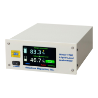
4. Connect the sensor to the instrument.
a. For distances of 6 feet and less, connect the coaxial cable (6)
between the BNC connector on the liquid level sensor and the
BNC connector on the back of the instrument labeled O/T (3).
b. For distances greater than 6 feet, connect the coaxial cable (9)
between the BNC connector on the liquid level sensor and the
BNC connector on the oscillator / transmitter (7). Use a second
length of coaxial cable (6) to connect between the oscillator /
transmitter (7) and the BNC connector on the back of the
instrument labeled O/T (3).
6 Coaxial cable connecting the oscillator / transmitter and the instrument
7 Oscillator / Transmitter (optional; refer to section 2.4.1 on page 13)
8 Level Sensor for level controlled or target dewar
9
Coaxial cable connecting the Oscillator / Transmitter and the liquid level
sensor (optional; refer to section 2.4.1 on page 13)
10 Fill port on target dewar
11
Transfer line attached to the target dewar and the fill solenoid valve on the
source dewar
12 Solenoid-operated fill valve
13 Supply dewar relief valve
14 Supply dewar
Table 2-1. Standard Autofill Setup Description
Number Item