Rev. 2 15
Installation
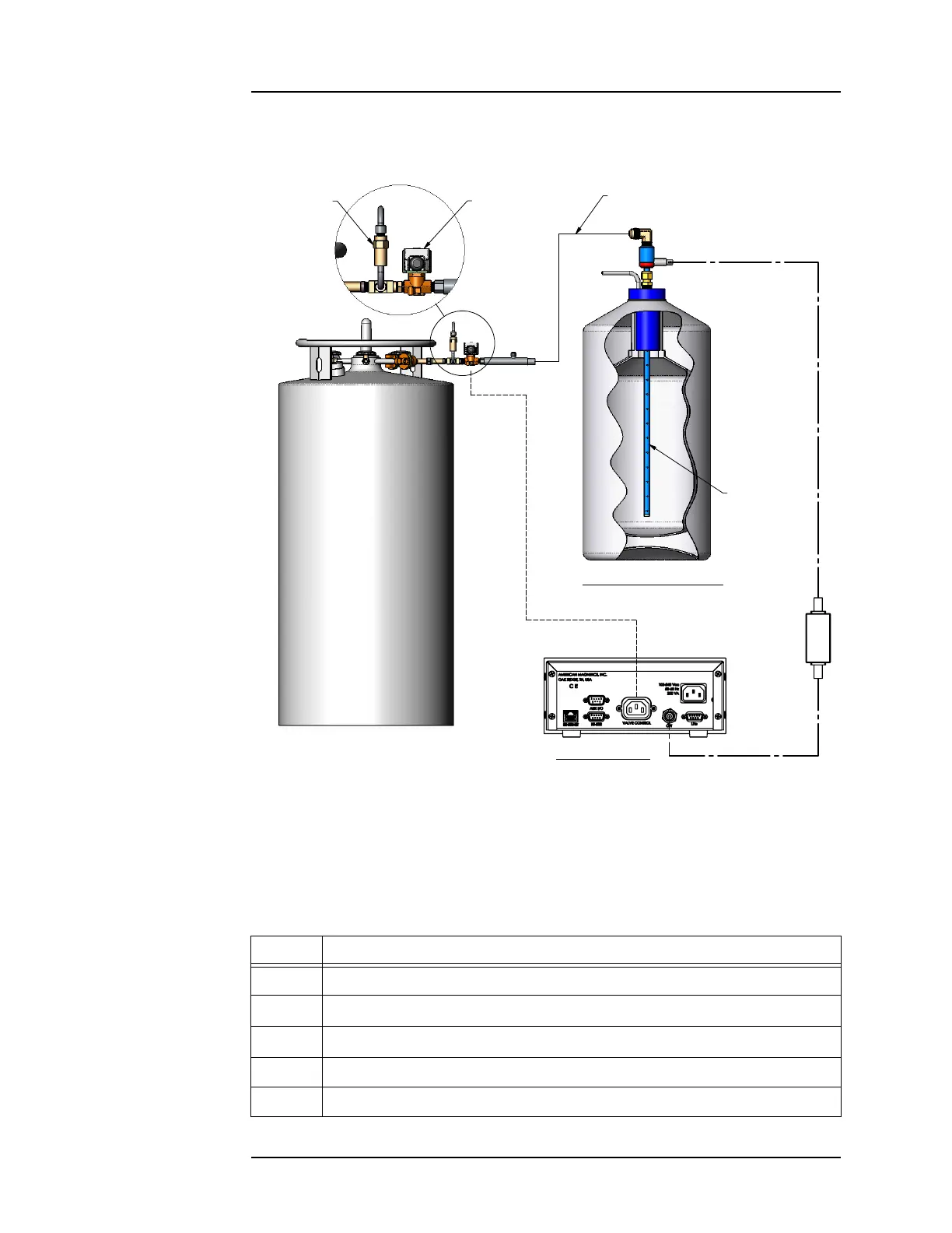
Setting Up an Autofill System
begin liquid transfer. The transfer is stopped when the measured level
reaches a user-determined point.
Table 2-1. Standard Autofill Setup Description
Number Item
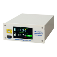
1 Model 1700 Liquid Level Instrument (Level Controller)
2
IEC60320 C13 socket labeled
VALVE CONTROL
3
BNC connector labeled
O/T
4 Solenoid-operated flow control valve line cord with IEC60320 C14 plug
5 Instrument IEC60329 C14 Power cord socket
Figure 2-1. Model 1700 Instrument in an Autofill configuration
6833/<'(:$5
/1/(9(/
6(1625
),//9$/9(
5(/,()9$/9(
26&,//$725
75$160,77(5
02'(//,48,'
/(9(/&21752//(5
/(9(/&21752//(''(:$5
&2$;,$/
&$%/(
75$16)(5/,1(
Figure 2-1. Typical Autofill Setup
7
8
9
6
1
12
14
13
11
10
3
2
5
4