17
Installation
Doc No: OMMC00296 Revision: 2 – Sept 2020
Section 5
Installation
WARNING
The valve is heavy; refer to 9.1.4. The appropriate manual
handling precautions must be applied to avoid personnel injury.
5.1 Installing the valve
5.1.1 Before starting installation
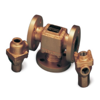
1. Upon receipt, the valve should be checked for damage
sustained in shipping. All AMOT valves have nameplates
attached, which are stamped with the valve model number
and serial number.
2. Understand the intended use of the valve as described in
Section 3.
3. Before installation, ensure that the valve is suitable for the
purpose, checking temperature, pressure and material
parameters, and any special approval requirements (refer to
Section 3.3). Check that the intended pipe fittings are
suitable for the application.
4. Check that the valve size has been selected in accordance
with the anticipated flow rate through the valve (refer to
Section 3.3). To maintain good temperature regulation the
pressure drop across the valve should be in the 0.14 to 0.5
bar (2 to 7 psi) range.
5. If the valve is to be fitted at a high point in the system, the
system should be vented to prevent trapped air around the
temperature elements.
6. For optimum temperature regulation the system should be
designed so that the element is in the mid-position under
nominal conditions. To achieve this, it may be necessary to
balance the fluid flow by inserting an orifice in the by-pass
circuit.
7. If appropriate, read and understand the legal requirements
of installing the valve within the European Union as
described in Section 4.