E
Emily WiseAug 5, 2025
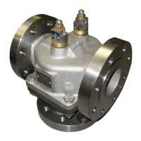
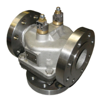
What to do if the AMOT G Series Control Unit valve is oscillating?
- PPhilip AlvaradoAug 5, 2025
If the valve is oscillating or moving in large steps, you can try the following: adjust PID values, adjust dead band settings, move the temperature sensor, adjust the deadband setting, adjust gears or pulleys, or replace the pin.