21
Electric Actuator
OMMGGE00217 Rev 4 – MAY 2019
4.1.3 Versions
The actuator is available in 115V ac and 230V ac versions, single phase only.
All EB actuators have the option of a Positioner, which is fitted inside the
terminal box (see Fig 6, page 21).
The internal wiring for the various options are illustrated in (Fig 7, page 23).
The external wiring is illustrated in the system wiring diagrams of Section 7,
page 65 (System Integration).
4.1.4 Optional Positioner
An optional Positioner is available, to control the actuator from a 4-20mA input
signal. The Positioner requires an optional Power Module to also be fitted.
The Actuator can be operated by direct mains switching or by a low level dc
current or voltage input when the optional Positioner is installed in the
Terminal Box.
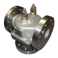
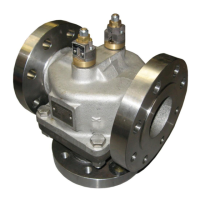
Fig 6 shows the internal arrangement of the Terminal Box with the Positioner
installed.
Fig 6 EB Actuator (Shown With Positioner)
The Positioner is a versatile, micro-processor controlled unit which is fully
configurable for various control functions. The configuration of the unit is
detailed in sections 4.5.1 (page 31) and 4.6 (page 33).
The main features of the Positioner are:
• Control of the actuator by an externally generated 4 – 20 mA signal.
• Actuator position indication available as 4 – 20 mA output (position re-
transmission).
• Status indicator LEDs.
• Two Alarm output signals to indicate actuator status:
• Alarm 1 normally closed, open for warning.
• Alarm 2 normally closed, open for fault.
Module
 Loading...