4.5 Fuel injectors 4 WIRING
4.4.8 Generic on/off switches
There are several inputs the MS3Pro can use as switch inputs for triggering launch control, nitrous, table switching,
or other functions. Valid inputs include the Digital Switched In inputs, the Digital Frequency In inputs, the Digital
I/O pins, and Digital Switched 12V In. Digital Switched 12V In activates when connected by a switch to a 12 volt
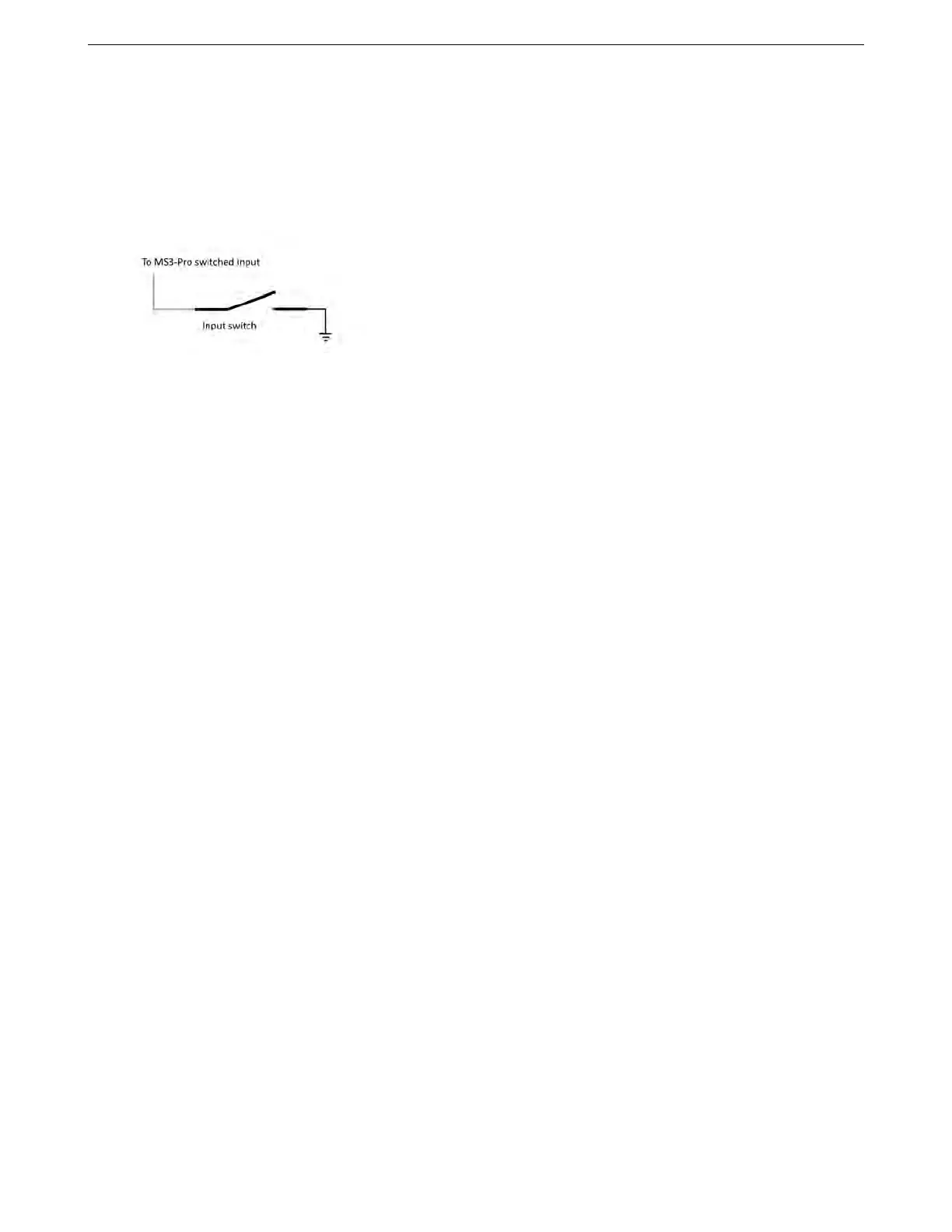
source. All other on/off switch inputs activate when connected through a switch to ground instead. The Digital
Switched 12V In function is set up this way to allow using it to detect when a nitrous system is energized and arm
the system, but can be used for other functions as well. The illustration below shows typical switched input wiring.
Caution: Do not wire the Digital Switched 12V In wire directly to any input that is supplying power to a trans
brake or other high powered solenoid. This may result in damage to the input circuit. Instead, use the 12 volt
power to the solenoid to switch a relay to control an on/off input.
4.4.9 Other sensors
You can connect any 0 to 5 volt analog signal to the Analog In inputs. The MS3Pro software can use these for data
logging or other functions.
4.5 Fuel injectors
Fuel injectors are pretty simple; one side gets switched, fused 12 volt power. The other side connects to the
MS3Pro injector output. They are not polarized so it doesn’t matter which is which. Current MS3Pro settings have
the firing order hard-coded in, so they always fire in alphabetical order.
If running sequential output on a 12 cylinder engine, High Current 1 and 2 fire the 11th and 12th injectors in the
firing order, respectively.
4.6 Ignition outputs
Ignition coils, as you probably know, require amps or tens of amps of current in order to work. The signal from
the MS3Pro is a much lower-power "logic-level" signal - the kind of signal seen inside computers. So some sort of
device is needed to allow the weak logic-level signal from the MS3Pro to drive the coils.
In other automotive scenarios, this might be done with a relay, which is commonly used to switch a high-power
signal from a source signal of lower power. But a relay isn’t suitable for driving a coil for a number of reasons,
so instead, there’s an electronic device called an ignition module, "ignitor," or "coil driver" to do the job. A few
manufacturers, such as Nissan, call the assembly a “power transistor,” which more properly refers to the electronic
component at the core of the coil driver device. Some coils have the ignitor built in; those coils have more than 2
wires because of the extra functions they contain. Simple coils without built-in ignitors usually only have 2 wires.
(There are exceptions, like the IGN-1 coils, which have an isolated secondary ground and use 3 wires.)
If you’re using a factory ignitor with matching factory coils, you can expect that the coils and ignitors are de-
signed to work together. If your coils require an ignitor but you do not have one, our QuadSpark ignition module
can drive most factory coils.
4.6.1 QuadSpark ignition module
Here are the pins to use on the QuadSpark.
AMP EFI MS3ProUltimate manual version 1.203, firmware 1.5.0, 5/23/2017 Page 47