4.2 Wiring diagram 4 WIRING
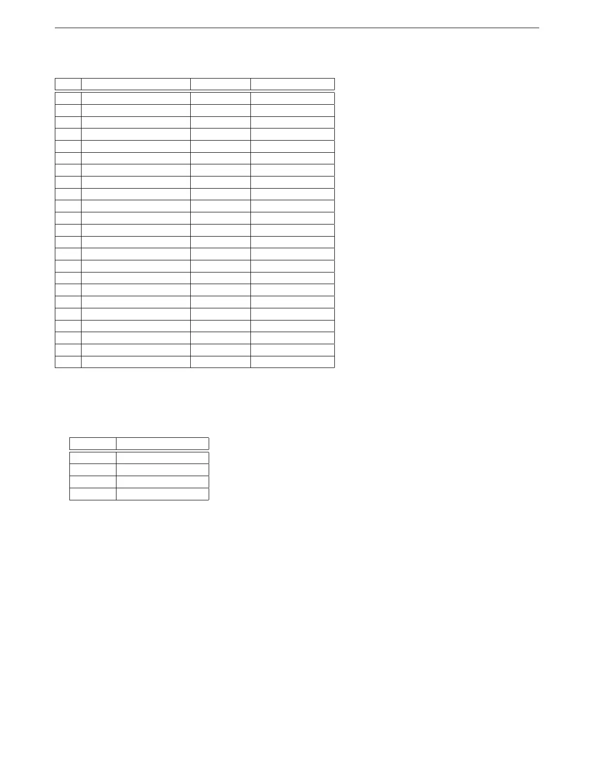
Black Connector Pinout
Pin Function Wire Color Stripe / shielding
1 PWM out 5 Light green Red
2 PWM out 4 Light green Orange
3 Digital out 2 Brown Dark blue
4 Digital out 1 Brown Dark green
5 Digital I/O 4 Brown Pink
6 Digital I/O 2 Brown Orange
7 Analog in 8 Light blue Purple
8 5V+ VREF out 2 Gray Black
9 Fuel only coil negative Black Red
10 Digital switched in 5 Gray Orange
11 Digital switched in 4 Gray Pink
12 Digital I/O 5 Brown Red
13 Digital I/O 3 Brown Light green
14 Digital I/O 1 Brown None
15 5V+ VREF out 2 Gray Black
16 Fuel only battery 12V+ Red Black
17 Sensor return Black White *
18 Sensor return Black White *
19 Sensor return Black White *
20 Sensor return Black White *
21 Sensor return Black White *
22 5V+ VREF out 1 Gray No stripe
23 Keep alive power Red White
* Some early production MS3Pro Ultimate harnesses are missing the white stripe.
RS232 serial cable
The pin names are marked on the connector.
M12 pin DB9 pin
1 9 (5 volt reference)
2 3 (Data)
3 5 (Ground)
4 2 (Data)
4.2 Wiring diagram
These show the basic connections - power, ground, fuel, ignition, idle control, and basic sensors. Other optional
inputs and outputs are covered in their respective sections.
AMP EFI MS3ProUltimate manual version 1.203, firmware 1.5.0, 5/23/2017 Page 35