Page 49
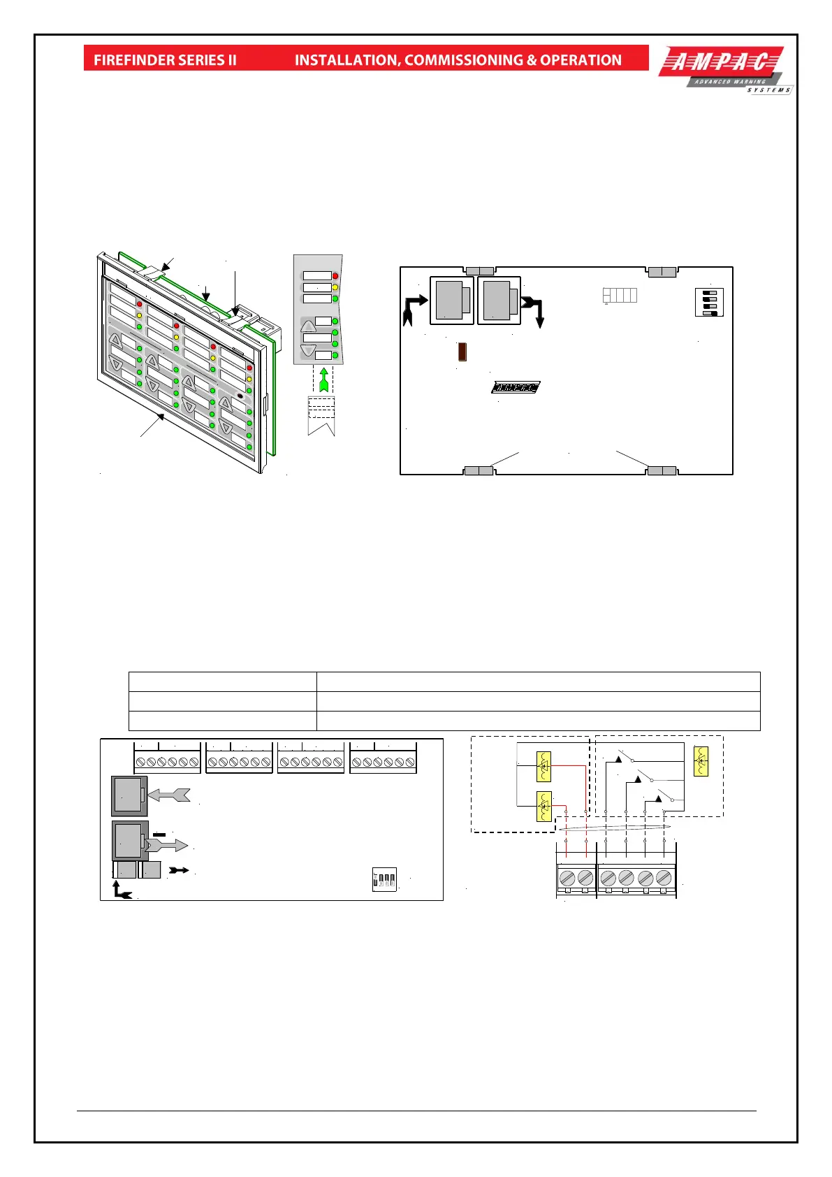
11.11 Fire Fan Module (BRD25FCB)
The Fire Fan Module has four (4) separate fan controls each having an On, Auto and Off function
switch and a set of three (3) monitoring LED’s. The LED’s indicate the status of the equipment e.g.
Run, Fault or Stop. The two (2) arrow head keys are used to step up and / or down through the three
(3) conditions. A slip in label can also be inserted into the hinged cover for identification purposes.
The “Plant Trip” Reset is used to locally restart plant and equipment that has been automatically shut
down because the FACP has initiated an alarm once that alarm has been cleared.
Quiescent Current: 13.5mA
Slip In
Label
Module & PCB Securing Tabs
( Top & Bottom )
PCB
Clear Plastic Clip In Label
Clip On
Plastic Surround
( Push down here and pull
out to remove and insert labels )
WINDOWS
WINDOWS
FOR SLIP
IN LABELS
Lettering on slip in
labels must be at
least 5mm in height.
ACTIVATED
PLANT TRIP
RESET
LK1
CN3
CN1
CN2
BRD25FCB4
LINK
TERMINATOR
In
Out
Address
Switch
Set to 1
1 2 3 4
ON
C
N
1
C
N
2
CN1: Communications & 27V IN from CN2 off the previous
Front Panel Card or CN20 on the Main Control Board
CN2: Communications & 27V OUT
to Next Front Panel Card.
If Unsed the Termination Link Must be Inserted.
PCB Securing Clips
Figure 59: Fire Fan Module Front Panel Figure 60: Fire Fan Module PCB Layout
11.12 Fan Termination Board (BRD25FTB)
The Fan Termination Board interfaces between the Fire Fan Module and the plant/equipment it
controls via the 24 volt 250mA Start, Stop, current limited, relay outputs and monitor inputs.
Programmable monitoring of the field equipment is achieved using 0 volts as an input level to
indicate run, fault and stop conditions of that equipment. Monitoring is programmed in the Function
Menu for a 3, 4 or 5 Wire Start / Stop, Run, Fault, Stop & Common functions. The inputs are
protected by way of resettable transorbs and resistive / capacitive networks.
Connectors
27VDC in and out on boards mounted external to the FACP
Factory programming only and may not be available on all boards
Connect the fan control and monitoring wiring to the board.
SW1
TB4
TB3
TB2
LK1
TB5
EOL Termination
0V +27V
POWER
Address SW
FAN 1FAN 1
STOP COMSTOPFLTRUN
FAN 2
STOP COMSTOPFLTRUNSTART
FAN 3
FAN 3
STOP COMSTOPFLTRUNSTART
FAN 4
COMSTOPFLTRUNSTART
FAN 4
STOP
START
FAN 2
CN1
CN2
CN3 CN4
RS485 Control in from CN2 of Previous
Board or CN21 of the Main Control Board
RS485 Control Out to Next Board or Link 1 EOL is Applied
27V In from the Brigade Broard or CN4 of the Previous Board
27V Out to Next Board if Applicable
1 2 3 4
ON
STOP
COM
STOP
FLT
RUN
START
TB 2, 3, 4 or 5
Cabling from FACP
to Plant / Equipment
1 2 3 4 5 6
FAN CONTROL
SOLID STATE OR
RELAY INTERFACE
FAN MONITORING
0V
INPUTS 1, 2 & 3
+24V O/Ps
RUN
STOP, START, RUN = 3 WIRE
STOP, START, RUN,
STOP = 4 WIRE
STOP, START, RUN, STOP,
FAULT = 5 WIRE
Figure 61: Fan Termination Board Layout and Typical I/O Wiring
 Loading...