Page 72
13.4 Setting the Address
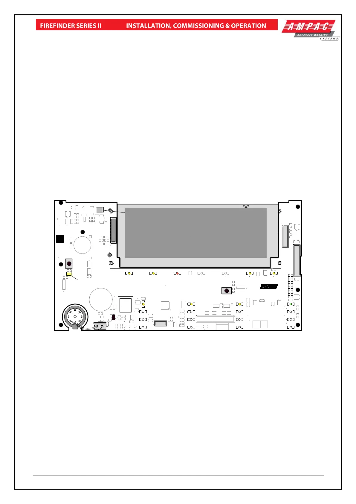
Open the front door; locate the “CONFIG” button situated on the left hand side of the PCB and press
for 3 seconds. The buzzer and “Config” LED will double beep and flash respectively to indicate that
the Configuration mode has been entered. The LCD will now display the Configuration screen. This
screen consists of the code version number, current address and four adjustment markers. These
markers A-, A+, C-, and C+ are used to indicate the keys that adjust the address and LCD contrast.
Use the “PREVIOUS (A-) and NEXT” (A+) keys to select the desired address. The default value for
this address is 255 which is not a valid SmartTerminal address. The user must then select an
address value from 1 to 30, i.e. the same address as that set in the FACP. The keys corresponding
to C- (ACK) and C+ (RESET) are used in a similar manner to decrease and increase the LCD
contrast level. There is audible feedback for all key presses.
Once the address has been set press the “CONFIG” button again for 3 seconds and the screen will
return to its default and the “DIANOSTIC” LED will return to a slow flash. This slow flash indicates
SmartTerminal and the FACP are communicating normally i.e. the LED flashes if communications
data is being received from the FACP.
Note: If the address is not set within the time out period of approximately 75 seconds
SmartTerminal will return to its normal state.
Note: Each SmartTerminal must have its own individual address.
CN5
TO
TERM
BRD
LCD
DIAGNOSTIC /
CONFIG LED
2
1
8
7
6
5
4
3
D24
CN12
CN11
CN10
BRD82ICC
Main Control PCB
CN7
PWR LINK
PWR LINK
KEYSWITCH
PRINTER
RESET
TOUCH HERE FIRST
DISCHARGE POINT
CONFIG
BRD82ICC2-
28/04/2006
R43
R42
SW27
SW28
Q2
R35
U11
BZ1
CN8
CN9
CN7
CN10
CN1
CN2
CN3
CN6
D2 D3 D4 D5 D6 D7 D8
D9
D10
D11
D12
D13
D14
D15
D16
D17
D18
D19
D20
D21
D22
D23
D29
D31D32
D35
LK1
Q4
Q6
Q1
Q5
R12
RN1
TH1
U12
U7
U8
U9
U4
U15
U6
U1
U14
U10
X1
RN13
U3
U2
U5
Q7
R45
R46
R47
FLASH
LCD BACKLIGHT
Figure 85: Main PCB Layout
 Loading...