7.2 Electrical Description:
The detectors are designed to be connected to a two wire loop circuit carrying both data and a 17V to 28V dc
supply. The detectors are connected to the incoming and outgoing supply via terminals L1 and L2 in the
mounting base. A remote LED indicator requiring not more than 4mA at 5V may be connected between +R
and -R terminals. An earth connection terminal is also provided.
When a device is energised the ASIC regulates the flow of power and controls the data processing. The
thermistor provides an output over normal operating ranges that is proportional to the external air
temperature. This voltage output is processed in the A/D converter and stored by the communications ASIC.
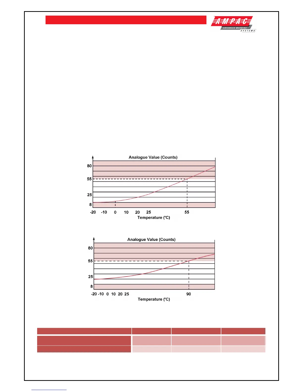
It is transmitted to control equipment when the device is interrogated. When a count of 55 is exceeded the
alarm flag is initiated and the device address is added to the data stream every 32 polling cycles from its last
polling for the duration of the alarm level condition, except when an alarming device is being interrogated.
This can provide a location identified alarm from any device on the loop in approximately two seconds. The
detector is calibrated to give an analogue value of 25±5 counts at 25°C.
7.3 Environmental Characteristics:
XP95 Standard Heat Detectors operate over the range -20°C to +70°C, the High Temperature Heat
Detectors operate over the range –20°C to +120°C. The detectors are unaffected by atmospheric pressure.
Figure 13 – Typical Response Characteristic – XP95 Standard Heat Detector A2S (55°C)
Figure 14 – XP95 High Temperature Heat Detector CS (90°C)
7.4 Product Codes
Product Description LPCB (EN54-5) SAI Global (AS7240-5) Activfire (AS1603-1)