Ampcontrol Pty Ltd – ABN 28 000 915 542
DIESELGUARD USER MANUAL
MAG-179 Version 3 – APR/16
Uncontrolled Copy - Refer to Ampcontrol Website for Latest Version
APPROVED FOR EXTERNAL DISTRIBUTION – PROPERTY OF AMPCONTROL PTY LTD – NOT TO BE REPRODUCED IN PART
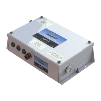
3.5 I.S. Solenoid Valve
Figure 3.4: I.S. Solenoid Valve
The IS Solenoid Valve is used to control the diesel machine’s pressure circuit based upon the outputs of
the Diesel Machine Monitor.
The I.S. Solenoid Valve can be mounted in any suitable location. The pneumatic connections are:
Ports 1 and 2 are normally connected when the solenoid is energised.
Ports 1 to 3 (the vent port) are connected when the valve is de-energised.
The valve should be connected so that the pressure is released from the downstream side of the valve
when de energised.
See manufacturer’s installation and maintenance sheet for additional information.
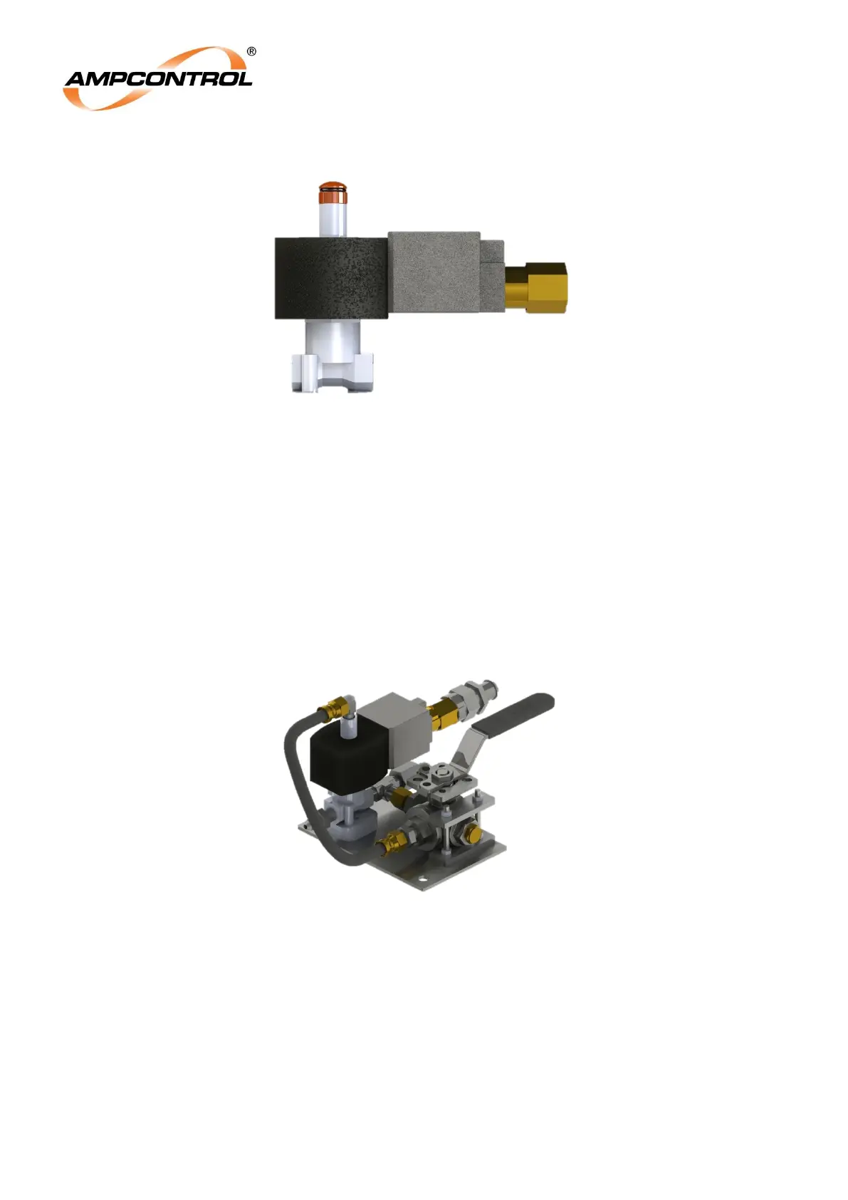
3.6 Pneumatic Bypass Assembly (c/w I.S. Solenoid Valve)
Figure 3.5: Pneumatic Bypass Assembly
The Pneumatic Bypass Assembly contains the I.S. Solenoid Valve as well as a manually operated valve.
The manually operated valve allows the operator to bypass the Dieselguard system in the event of a flat
battery in the Diesel Machine Monitor.