Ampcontrol Pty Ltd – ABN 28 000 915 542
DIESELGUARD USER MANUAL
MAG-179 Version 3 – APR/16
Uncontrolled Copy - Refer to Ampcontrol Website for Latest Version
APPROVED FOR EXTERNAL DISTRIBUTION – PROPERTY OF AMPCONTROL PTY LTD – NOT TO BE REPRODUCED IN PART
4.4 Electrical Installation Information
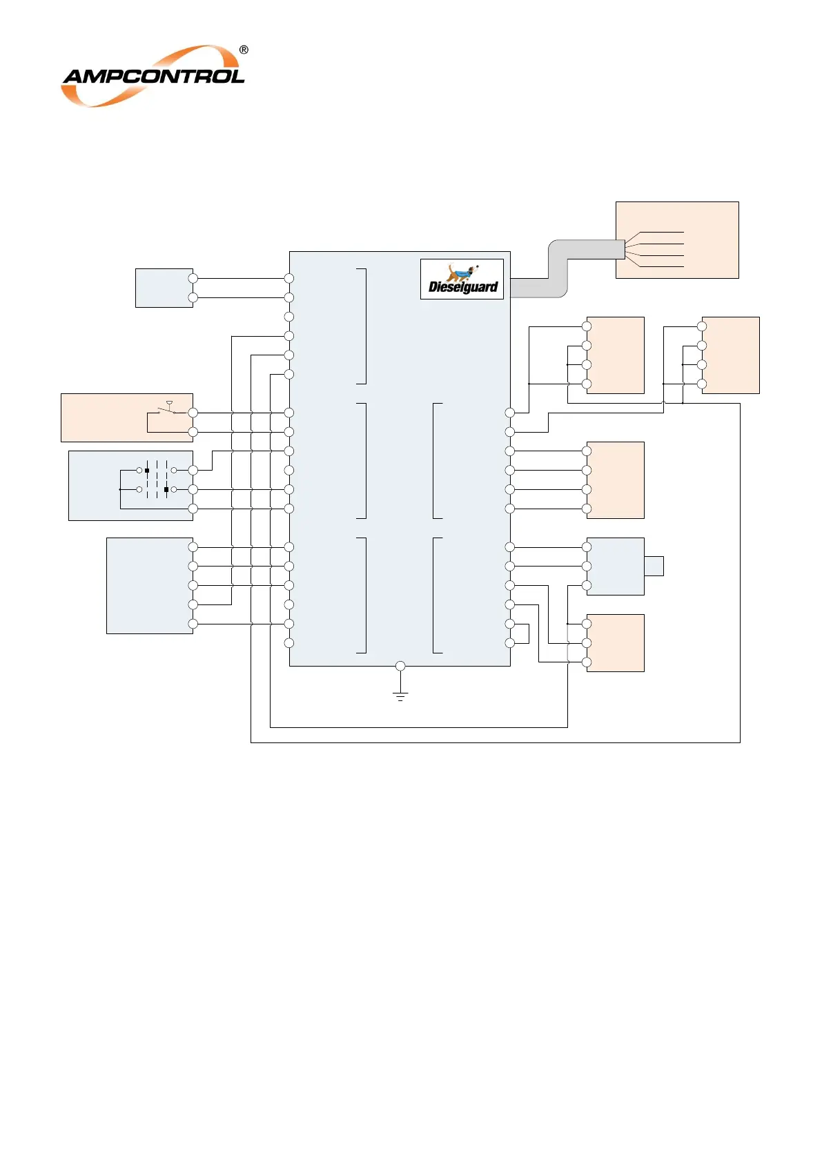
Figure 4.5: Typical Connection Diagram for the Dieselguard System
With the exception of the encapsulated flying lead, all of the connections to the Diesel Machine Monitor
are IS circuits and should be wired accordingly. In some locations it may be necessary to protect IS
cabling from mechanical damage. The unit is not supplied with interconnecting cables; the installer is
responsible for providing cabling to suit the application.
Customer Supply
(Alternator)
Ex ‘d’ or Ex ‘e’ Enclosure
Dieselguard Diesel Machine Monitor
Control
Enclosure
0V
TERM 1 TERM 2 TERM 3
TERM 4 TERM 5
PT100 (RTD1)
RED1
WHITE1
WHITE2
RED2
RTD1 Drv
RTD1 Ref
RTD1 LO
RTD1 HI
RTD3
PT100 (RTD3)
RED1
WHITE1
WHITE2
RED2
PT100 (RTD2)
RED1
WHITE1
WHITE2
RED2
RTD2
4-20mA IN
0V
SPEEDO
0V
OIL
0V
CH4 Transmitter
4-20mA
0V
+
Speed Sensor
+
Output
-
Term1: Sensor V+
IDA Display
Pressure Operated
Start Switch
RST DEP
RUN
ASCO Solenoid
0V
Red (12V)
Green (12V)
4-20mA Signal
ALARM RESET
0V
DEPUTY
0V
IDA SIGNAL
0V
IDA RED
0V
IDA GRN
0V
RUN
0V
0V
SOL V+
0V
SOL V+
IDA V+
0V
SENSOR V+
12V
Term1: 0V
V+ (Core 4)
V- (Core 3)
V- (Core 2)
V- (Core 1)
Type 2S
4 Core Cable
(Encapsulated)
Integrated or
Remote CH4
Sensor
EARTH STUD