Ampcontrol Pty Ltd – ABN 28 000 915 542
DIESELGUARD USER MANUAL
MAG-179 Version 3 – APR/16
Uncontrolled Copy - Refer to Ampcontrol Website for Latest Version
APPROVED FOR EXTERNAL DISTRIBUTION – PROPERTY OF AMPCONTROL PTY LTD – NOT TO BE REPRODUCED IN PART
4.4.1 Power Supply
The power supply connection for the Diesel Machine Monitor is via the 3 metre 4 core Type 2S flying
lead. This cable must be terminated into a suitable Ex ‘d’ or Ex ‘e’ enclosure and is intended to be
connected to the alternator supply. The installer would typically gland this cable into the hours run
enclosure, but if all the gland entries are already allocated, a separate enclosure may be required.
The Diesel Machine Monitor can be powered from a nominal 12-24V supply. The unit is designed to
operate on an AC/DC supply of 9.5 - 36V but will withstand 90V. The input to the Diesel Machine
Monitor is isolated from the enclosure for use with non-earthed alternator systems.
Cores 1, 2 & 3 of the Type 2S cable should ideally connect to 0V. Core 4 of the Type 2S cable should
be connected to the +ve of the alternator supply. The Dieselguard system is not polarity sensitive, thus
the connections can be reversed if required. The polarity markings are present for variants with a non-
isolated 0V referenced input supply.
The apparatus must be installed such that the integral wires are
terminated in a suitably certified Ex ‘e’ or Ex ‘d’ enclosure having a
minimum Ingress Protection (IP) rating of IP55. If the wires are
terminated in an Ex e enclosure suitably certified Ex e terminals must
be used for terminating the wires.
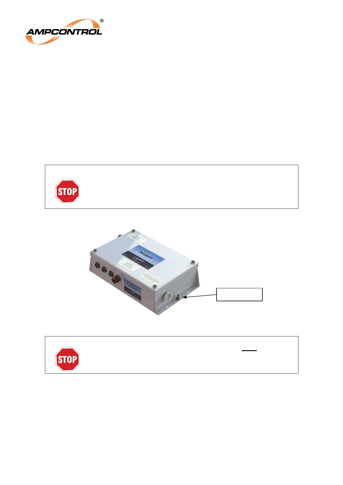
4.4.2 Earth Stud
Figure 4.6: Location of the Earth Stud on Diesel Machine Monitor
The Diesel Machine Monitor has an earth stud that must be infallibly
connected to the chassis of the vehicle to comply with the
certification requirements.
4.4.1 Solenoid Output (Terminal Block 1: SOL V+)
The control solenoid for the Dieselguard System should be connected between the SOL V+ output and
0V on Terminal Block 1. The Diesel Machine Monitor will energise this output when the system is in the
healthy state, or when the Deputy Override Switch is activated.
The solenoid output is 24Vdc and is current limited to 84mA.