Ampcontrol Pty Ltd – ABN 28 000 915 542
DIESELGUARD USER MANUAL
MAG-179 Version 3 – APR/16
Uncontrolled Copy - Refer to Ampcontrol Website for Latest Version
APPROVED FOR EXTERNAL DISTRIBUTION – PROPERTY OF AMPCONTROL PTY LTD – NOT TO BE REPRODUCED IN PART
4.3 Mechanical Installation Information
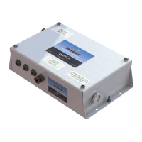
4.3.1 Enclosure Dimensions
Figure 4.1: Diesel Machine Monitor Dimensions
4.3.2 Mounting Arrangements
The Dieselguard Diesel Machine Monitor can be mounted in any orientation without affecting its
operation. Since the unit does not require routine servicing, it can be mounted in a position that is not
normally accessible.
The lid of the enclosure must be fitted correctly with the Dubbo seals and M6 stainless steel button
head screws tightened to at least 0.1Nm. This is required to comply with the certification and IP rating.
Space should be allowed to ensure the lid is fitted correctly and the screws are torqued as required.
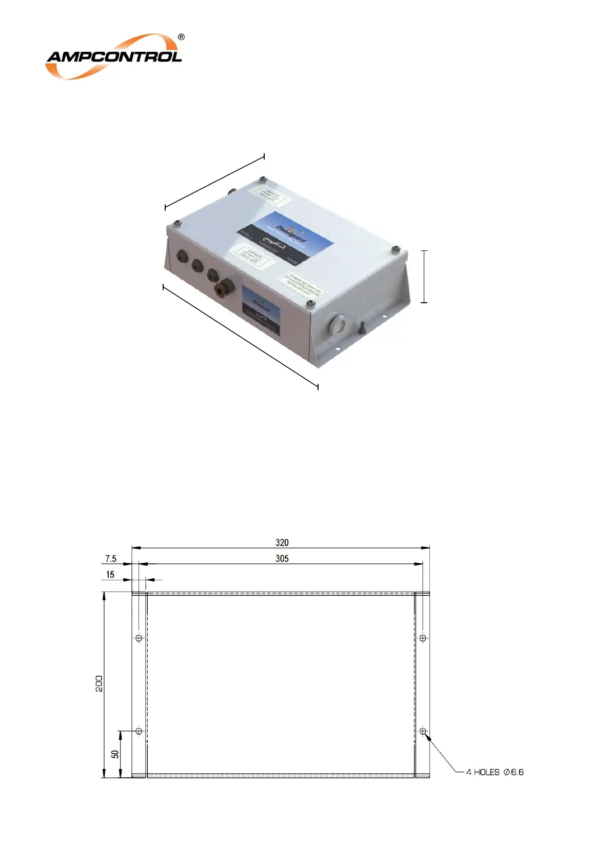
Figure 4.2: Mounting Hole Locations