Ampcontrol Pty Ltd – ABN 28 000 915 542
DIESELGUARD USER MANUAL
MAG-179 Version 3 – APR/16
Uncontrolled Copy - Refer to Ampcontrol Website for Latest Version
APPROVED FOR EXTERNAL DISTRIBUTION – PROPERTY OF AMPCONTROL PTY LTD – NOT TO BE REPRODUCED IN PART
TABLE OF FIGURES
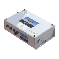
Figure 3.1: Diesel Machine Monitor ...................................................................... 8
Figure 3.2: Gasguard Transmitter with Integrated CH4 Sensor .......................... 10
Figure 3.3: IDA Display ...................................................................................... 10
Figure 3.4: I.S. Solenoid Valve ........................................................................... 11
Figure 3.5: Pneumatic Bypass Assembly ........................................................... 11
Figure 4.1: Diesel Machine Monitor Dimensions ................................................. 14
Figure 4.2: Mounting Hole Locations .................................................................. 14
Figure 4.3: Terminal Layout for Diesel Machine Monitor ..................................... 15
Figure 4.4: Isometric View of Diesel Machine Monitor’s Terminal Block ............. 15
Figure 4.5: Typical Connection Diagram for the Dieselguard System ................. 16
Figure 4.6: Location of the Earth Stud on Diesel Machine Monitor ..................... 17