Ampcontrol CSM Pty Ltd - ABN 35 000 770 141
ECD User Manual
ECDB005R0 13/03/2020 13:12 Page 12 of 21
4.2 Electrical Connections
Once the ECD relay has been mounted at a suitable location, it is necessary to wire it correctly.
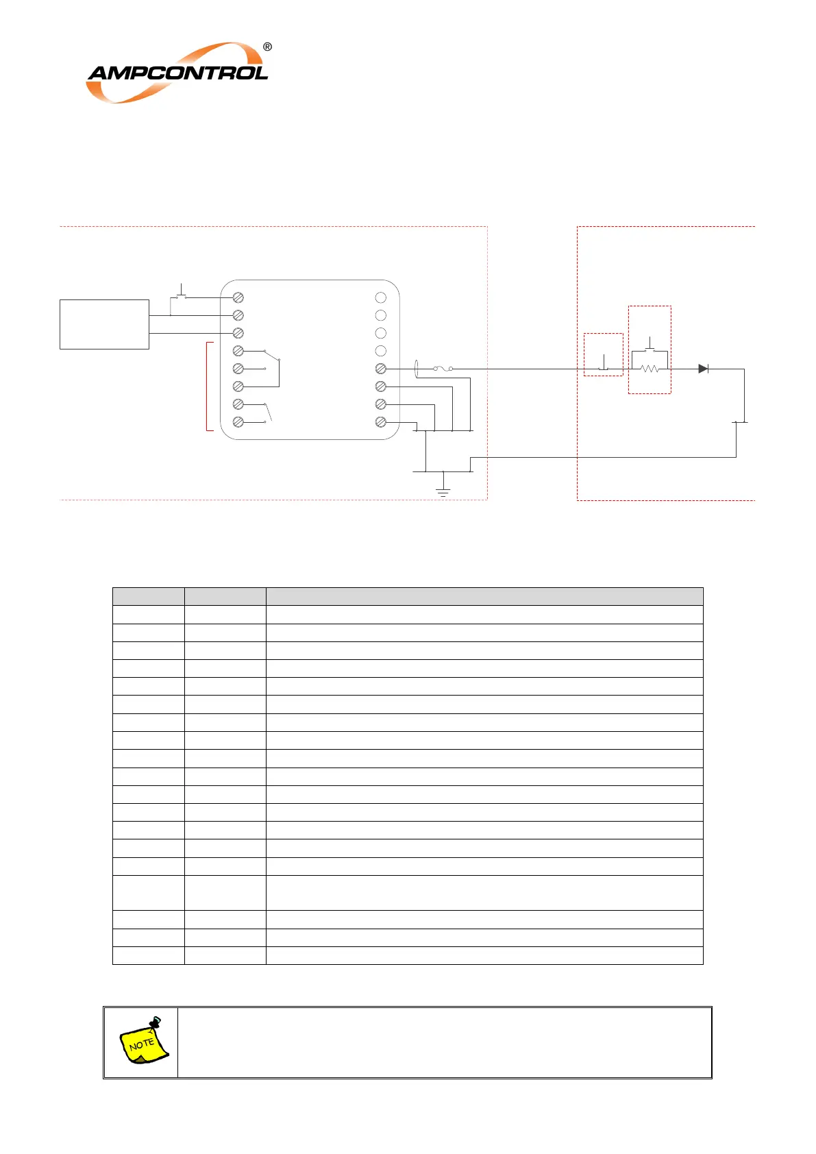
Figure 3 shows a typical wiring diagram for the application of the ECD relay. Also refer to drawing ECDM003 for installation
information.
N.O. USER
PUSHBUTTON
RST
PILOT
IS EARTH
IS EARTH
IS EARTH
+
-
D.C. SUPPLY
USER
DEFINED
SAFE AREA
HAZARDOUS
AREA
SAFE AREA
OPTIONAL
STOP
DIODE
1000V, 1A
OPTIONAL
REMOTE
START
RESISTOR
100Ω
IS EARTH
BAR
MAIN EARTH
BAR
TERMINATION
EARTH BAR
Figure 3: ECD Typical Electrical Application
The table below lists the terminal connections into the ECD relay.
Relay Output Normally Closed Contact 1
Relay Output Normally Open Contact 1
Relay Output Common Contact 1
Relay Output Normally Open Contact 2
Relay Output Common Contact 2
13 Pilot
IS Pilot connection (protected by internal IS barrier) (Single core screened,
screen connected to earth at ECD end)
Using a screened cable helps in reducing the induced / coupled voltages. This noise
can cause spurious trips.