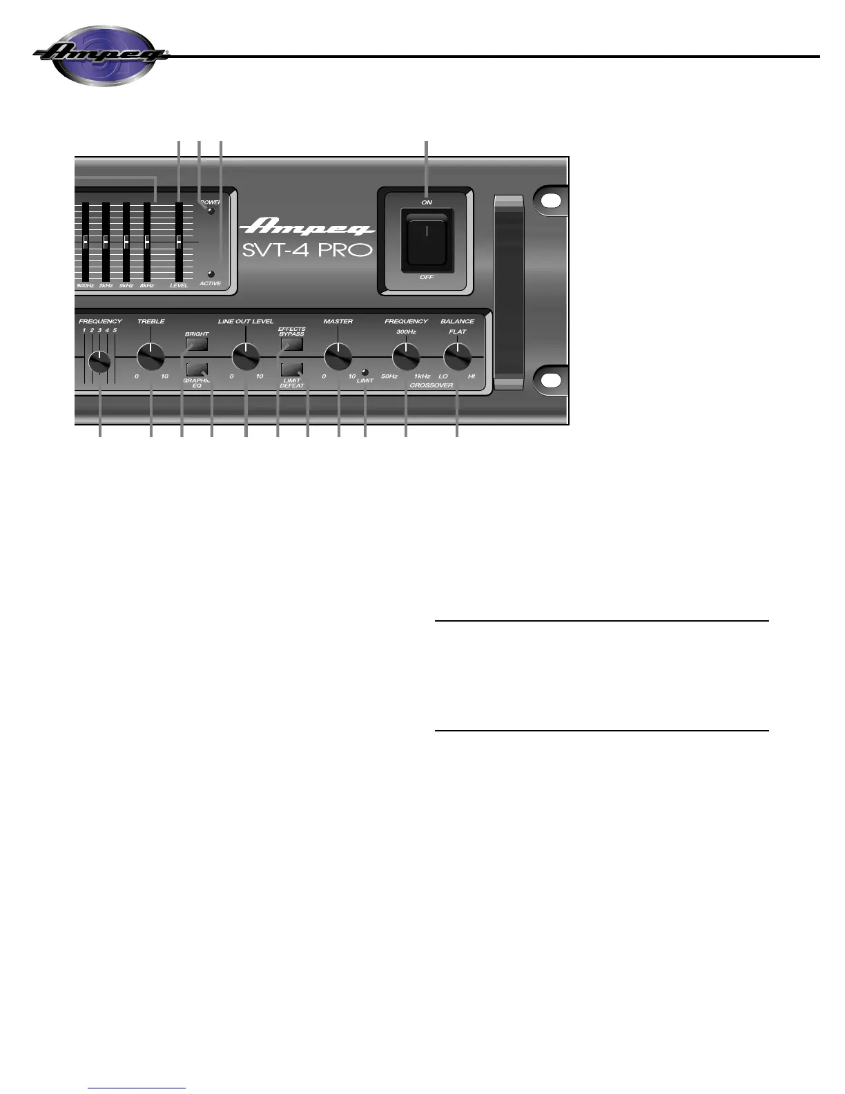
15. GRAPHIC EQ: This switch, when depressed, enables the
9-band Graphic EQ (see #23 and 24). The sound of your bass
will only be affected by the settings of the EQ slider controls
when this switch is depressed, or when a footswitch is
pressed. (A footswitch will override the front panel switch.
Please refer to #38, rear panel.)
16. LINE OUT LEVEL: This controls the strength of the signal
at the Line Out jacks (#40,41,44,45, rear panel).
17. EFFECTS BYPASS: This switch, when depressed, bypass-
es the Effects Loop. (A footswitch will override the front panel
switch. Please refer to #38, rear panel.)
18. LIMIT DEFEAT: The SVT-4 PRO employs internal limiter
circuits to help keep the power amplifier’s output clean at
extreme volume levels. (All amplifiers may begin to clip their
output signals as they approach maximum output levels,
resulting in potentially speaker-damaging distortion.) These
circuits may be defeated by depressing this switch, which may
result in an increase in output power but with the possibility of
distortion. Use discretion whenever playing with the Limit cir-
cuits defeated.
19. MASTER: This controls the overall output level of the
amplifier. For the best results, adjust the Gain control as
directed (see #5) and use this control to obtain the desired vol-
ume level.
20. LIMIT LED: This LED will flash any time the internal limit
circuit is called upon to keep the amplifier’s output signal
clean. This indicates that the amplifier is nearing full output
and the limiter is keeping it from clipping the output signal.
21. CROSSOVER FREQUENCY: This sets the crossover
point between the Biamp High and Biamp Low Outputs when
using the amplifier in the biamp mode. (See page 13.)
22. CROSSOVER BALANCE: This adjusts the relative level
between the low and high frequency biamp signals when
using the amplifier in the biamp mode.
23. 9-BAND GRAPHIC EQ: These sliders control the ampli-
tude of the signal at the frequency indicated below each con-
trol. The center position of each control is flat: sliding the con-
trol upward will increase the output signal level of that fre-
quency; sliding the control downward will decrease it.
The Graphic EQ can be used in two ways: 1) To fine tune your sound,
make small adjustments at the desired frequencies and leave the EQ
on throughout the entire session. (This is great for adapting to vary-
ing room acoustics when going from club to club, etc.) 2) For a com-
pletely different sound, make larger adjustments and only activate
the EQ when you want a “second channel” sound (such as during
bass solos).
24. LEVEL: This is the output volume control for the Graphic
EQ and only affects the signal when the EQ is engaged. If the
EQ’d signal is too soft, slide the Level control up; if it’s too
loud, slide the control down.
25.POWER LED: This LED illuminates green when the
Power switch (#27) is depressed.
26. ACTIVE LED: This LED illuminates when the Graphic EQ
switch (#15) is depressed.
27.POWER: This heavy-duty rocker switch applies AC power
to the amplifier: the amp is ON when the top of the switch is
depressed, OFF when the bottom of the switch is depressed.
 Loading...