SVT-4 PRO Bass Guitar Amplifier
6
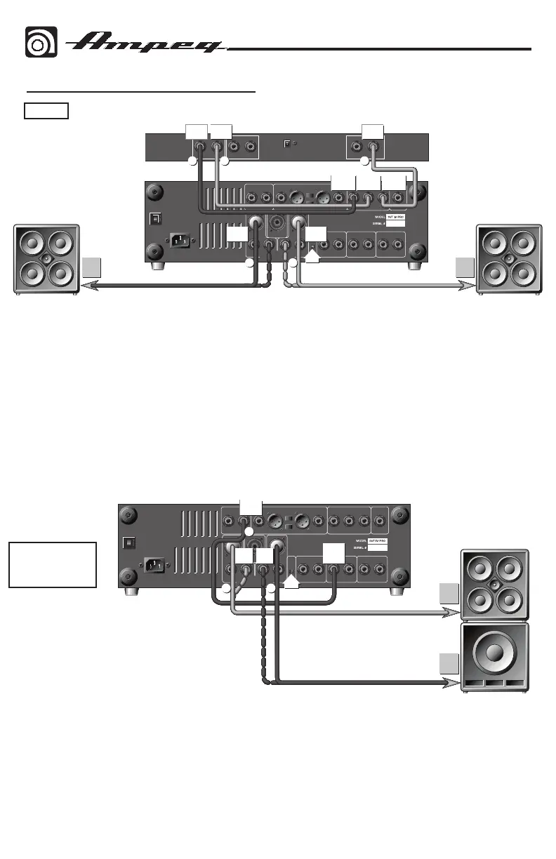
Hook-up Diagrams continued
In this example, the SVT-4 PRO’s two internal power amplifiers will each power a set of
full range cabinets in stereo. Disengage the Stereo/Mono Bridge switch [Stereo position].
Connect a shielded cable from the Effects Send of the SVT-4 PRO to the input of a stereo
effects processor. Next, connect a shielded cable from the left output of the processor to
the SVT-4 PRO’s Effects Return Left / B jack. Connect a shielded cable from the right output
of the processor to the SVT-4 PRO’s Effects Return Right / A jack. Now connect a speaker
cable from the SVT-4 PRO’s Power Amp A Speaker Output jack to the input jack(s) of the stage
left speakers. Finally, connect a speaker cable from the SVT-4 PRO’s Power Amp B Speaker
Output jack to the input jack(s) of the stage right speakers.
Note: For Speakon connectors pin 1+ = “+”, pin 1– = “–”.
Stage
Right
Cabinet(s)
Stage
Left
Cabinet(s)
Stereo Effects ProcesorStereo
SVT-4 PRO
PWR
AMP B
TO
INPUT
JACK
PWR
AMP A
TO
INPUT
JACK
OUT
(STEREO)
LEFT
OUT
RIGHT
OUT
INPUT
EFX RET
LEFT/B
EFX RET
RIGHT/A
EFX
SEND
32 1
45
Bi-amp: Full
Range / Lows
In this example, the SVT-4 PRO’s two internal power amplifiers will power both a full
range cabinet and a low frequency cabinet. The crossover point for the low frequency cabinet
is determined by the Crossover Frequency control [21]. Disengage the Stereo/Mono Bridge
switch [Stereo position]. Connect a shielded cable from the SVT-4 PRO’s Bi-amp Low Out jack
to its Power Amp A Power Amp In jack. Next, connect a speaker cable from the SVT-4 PRO’s
Power Amp A Speaker Output jack to the input jack of the low frequency cabinet(s). Finally,
connect a speaker cable from the SVT-4 PRO’s Power Amp B Speaker Output jack to the input
jack of the full range cabinet(s).
SVT-4 PRO
Full
Range
Cabinets
POWER
AMP A
P.A. IN
TO
INPUT
JACK
TO
INPUT
JACK
BIAMP
LO OUT
OUT
(STEREO)
PWR
AMP B
PWR
AMP A
1
3 2