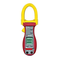
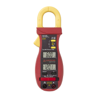
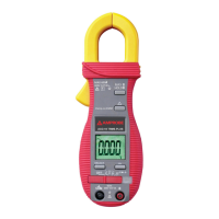
This document is a user manual for the Amprobe ACD-6 PRO and ACD-6 TRMS-PRO Professional 1000A Clamp Meters.
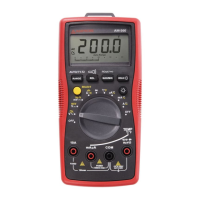
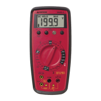
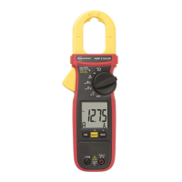
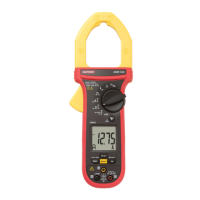
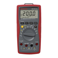
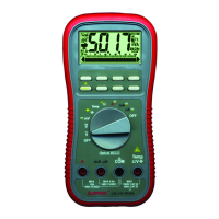
The Amprobe ACD-6 PRO and ACD-6 TRMS-PRO Clamp Meters are autoranging 1000 ACA / 600 V clamp meters designed for professional use. These instruments are capable of measuring AC/DC voltage, AC current, resistance, continuity, and performing diode tests. The ACD-6 TRMS-PRO model offers True RMS sensing for more accurate measurements of non-sinusoidal waveforms.
Function Description:
The clamp meter features a transformer clamp jaw for AC current magnetic field pick-up, allowing for non-invasive current measurements. It has a 3-3/4 digits, 4000 counts LCD display for clear readings. A function selector and power ON/OFF switch are used to choose the desired measurement mode and control the device's power. Input jacks are provided for all functions except AC current, with a dedicated common (ground reference) input jack. Push-buttons are included for special functions and features, enhancing the meter's versatility.
Usage Features:
- AC Current Measurement: To measure AC current, the function switch is set to the A~ position. The spring-loaded clamp is opened by pressing a lever on the left side of the meter, positioned around a single wire or conductor, and then released. The measured current value is then displayed. It is crucial to clamp the jaws around only one single conductor for load current measurement; more than one conductor will lead to false readings. Jaw center indicators and jaw marking lines are present to help position the conductor for best ACA accuracy and to indicate potential position errors.
- DC Voltage Measurement: For DC voltage measurements, the function switch is set to V=. Test leads are connected (red to +, black to COM), and the test probes are applied to the circuit test points. The display shows the voltage reading, with overload (OL) conditions indicated if necessary.
- AC Voltage Measurement: Similarly, for AC voltage measurements, the function switch is set to V~. Test leads are connected, and probes are applied to the circuit test points to obtain the reading.
- Resistance Measurement: To measure resistance, the function switch is set to Ω. Test leads are connected, and power to the circuit being measured must be turned off. Any capacitors that might influence the reading should be discharged. The test probes are then connected across the resistance. If "OL" appears on the highest range, the resistance is too large or the circuit is open.
- Continuity Testing: For continuity testing, the function switch is set to Ω, and the SELECT button is pressed until the continuity symbol ())) is displayed. After connecting test leads and ensuring the circuit is unpowered and capacitors discharged, probes are connected across the resistance or two test points. An audible tone indicates continuity (between 10 Ω and 120 Ω).
- Diode Testing: To test diodes, the function switch is set to Ω, and the SELECT button is pressed until the diode symbol is displayed. Test leads are connected, the circuit is unpowered, and at least one end of the diode is freed from the circuit. Probes are connected across the diode. A good diode typically shows a forward voltage drop of about 0.6 V, while an open or reverse-biased diode will read "OL".
- Manual or Auto-ranging: The meter supports both manual and auto-ranging. Pressing the RANGE button for more than 1 second toggles auto-ranging on or off. Momentarily pressing the button in manual mode allows stepping through the available ranges.
- HOLD Function: The HOLD button enables or disables the reading hold function. Once a reading stabilizes, pressing this button will freeze the value on the display, allowing the user to remove the test leads and still view the measurement.
- Relative Mode (▲): The ▲ button activates or deactivates relative mode. In this mode, the displayed reading becomes a reference value, and subsequent measurements are shown as the difference between the current reading and the stored reference value (display = measured reading - stored value).
- Auto Power Off (APO): To conserve battery life, the meter automatically enters sleep mode after approximately 30 minutes of inactivity. To wake it up, the slide-switch should be moved to OFF and then back to the desired function.
- Safety Features: The device includes a hand/finger barrier to indicate safe access limits during measurement. It conforms to various international safety standards (IEC/EN/UL 61010-1, CAN/CSA C22.2 No.61010-1-12, IEC/EN 61010-2-032, IEC/EN 61010-2-033, IEC/EN 61010-031) for Measurement Category III 600 V. Users are advised to keep hands/fingers behind the barriers, inspect test leads for damage, and use appropriate protective equipment when working with hazardous live conductors.
Maintenance Features:
- Troubleshooting: If a malfunction occurs, users should first check the battery, review operating instructions for potential errors, and inspect test leads for broken or intermittent connections.
- Cleaning: The front panel and case can be cleaned with a mild solution of detergent and water, applied sparingly with a soft cloth, and allowed to dry completely. Aromatic hydrocarbons or chlorinated solvents should not be used.
- Battery Replacement: The meter uses a 3V coin battery (ANSI/NEDA-5004LC, IEC-CR2032). To replace it, the meter's test leads must be disconnected from any circuit, the meter turned off, and the battery cover removed by unscrewing it. The old battery is replaced with a new one of the same type, observing polarity. The rear case and screws are then replaced. This procedure should be performed in a clean environment to avoid contaminating internal components.
- Repair: Except for battery and test probe replacement, repairs should only be carried out by a Factory Authorized Service Center or other qualified instrument service personnel.