18
4.1 GFCI-Protected Circuit Wire Tracing: Connecting the AT-6000-T Transmitter to
GFCI Protected Circuits
Connecting the Transmitter to an Energized GFCI protected circuit using a separate ground
method will trip the GFCI protection. Use the following methods to work with GFCI
protected circuits. For a De-energized GFCI-protected outlet that is not tripped, you can
connect test leads directly to the outlet contacts using the De-energized Tip Sensor mode.
Method 1 – Bypass the GFCI circuitry to avoid tripping GFCI:
(for Energized GFCI-protected outlets only)
• Remove the protective receptacle wall plate.
• Using the alligator clip, attach the red test lead to the screw to connect the Energized
hot wire to the receptacle.
• Connect the green test lead using a separate ground method.
• Perform tracing as described in the Quick Scan or Precision Tracing sections.
Method 2 – Do NOT use separate ground to avoid tripping GFCI:
(for GFCI-protected outlets and breakers)
• Connect the Transmitter with the test leads to the Neutral and Hot wires.
• Perform tracing as described in one of the following modes: Quick Scan, Precision
Tracing or Breaker Locating.
Note: This type of connection causes signal coupling and reduces signal strength. If the
signal is too weak or untraceable, use Method 3.
Method 3 - De-energize the circuit:
(for GFCI-protected breakers)
• Connect the Transmitter directly to the wire as described in wire tracing modes (Quick
Scan and Precision).
• Perform tracing as described in one of the following modes: Quick Scan, Precision
Tracing or Breaker Locating.
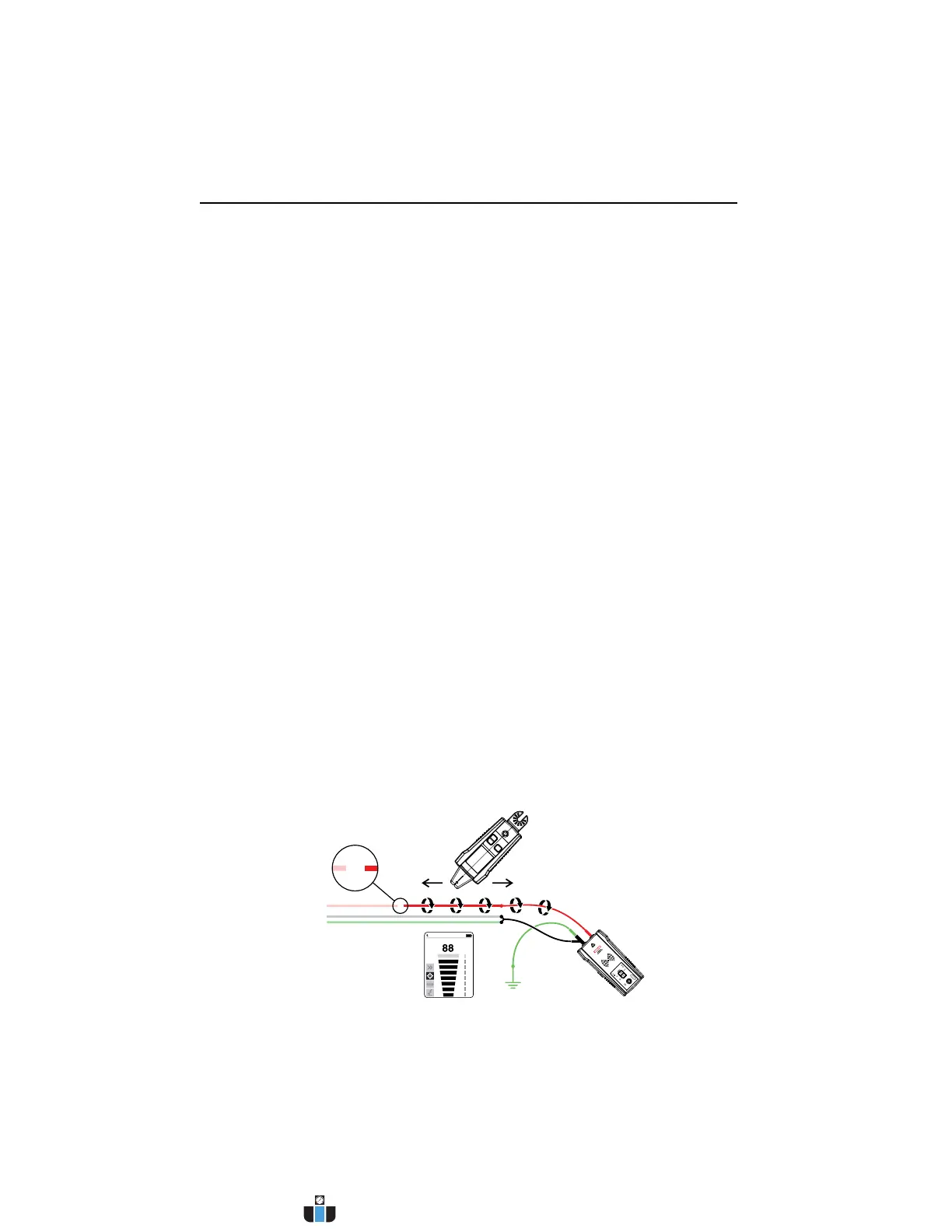
4.2 Finding Breaks/Opens
It is possible to pinpoint the exact location where a wire is broken using the Precision
Tracing mode, even if the wire is located behind walls, floors or ceilings.
1. Make sure that wire is De-energized.
2. Use the steps described in the Precision Tracing mode to connect the Transmitter and
perform tracing.
3. For best results, ground all De-energized wires that run in parallel with the black test lead.
4. SPECIAL APPLICATIONS
Figure 4.2: Locating a break or open
www.calcert.com sales@calcert.com1.800.544.2843
0
5
10
15
20
25
30