EasyManua.ls Logo

Amprobe TMD Series - User Manual

Amprobe TMD Series
11 pages
Print Icon
To Next Page IconTo Next Page
Loading...
OPERATING INSTRUCTIONS
MODEL TMD SERIES
SOFTWARE
and
USB/Wireless DRIVER
Install USB Driver:
For WINDOWS VISTA_XP
_2000 and USB Driver’s
Installation
1. Connect meter to PC with USB
cable. Following dialogue box will
appear automatically. Please
select “Install USB [for
WINDOWS7_VISTA_
XP_2000“to install.
2. Installation.
Install PC software:
1. Put the disk in the disk drive.
Following dialogue box will
appear automatically. Please
execute the “autorun.exe” if it
does not appear.
2. Button explanations
Single Meter [Wireless & Line] :
Install pc software for Single
Meter.
Multi Meter [Wireless & Line] :
Install pc software for Multi
Meter.
INSTALL USB driver (for
WINDOWS 7_
VISTA_XP_2000): Please refer
to the METER and USB
DRIVER’S
Instruction Manual: Operation
instruction manual.
EXIT: Exit install program.
Single / Multi Meter installation
window.
V1. 011008
1492-00800UW-02
Question and Answer IconNeed help?

Do you have a question about the Amprobe TMD Series and is the answer not in the manual?

Summary

Software and USB;Wireless Driver Installation

Install USB Driver for Windows Vista;XP;2000

Guide for installing USB drivers for Windows Vista, XP, and 2000.

Install PC Software from Disk

Instructions for installing the PC software using the provided disk.

PC Software Button Explanations

Explains buttons like Single/Multi Meter, USB Driver, Instruction Manual, and Exit.

Connection Port Management

Check Connection Port Procedure

Steps to check the connection port starting from Control Panel, Device Manager.

Uninstall USB Driver

Steps to uninstall the USB driver via Add or Remove Programs.

Single Meter PC Software Operation

Main Display Window Overview

Overview of the main display window after PC software startup.

Communication Port Setup Dialog

Explains the initial communication port setup dialogue for connecting the meter.

Toolbar Function Explanations

Details toolbar icons like File, Setup, Display, and Data Download.

Wireless Meter ID and Channel Settings

Guide for setting Meter ID and Channel for wireless models.

PC Software Configuration and Settings

Environment, Time, and Dongle Settings

Configures environment, time sync, and wireless dongle ID.

Alarm, Channel, and Y-Axis Display Settings

Sets Hi/Lo limits, alarm sounds, channel display, and graph Y-axis.

Data Logging Setup and Control

Instructions for setting up data logging and stopping the process.

Data Export and Meter Status

Export Stored Data to PC

How to export stored data from the meter to the PC using the export icon.

Wireless Signal Strength Indication

Displays received signal strength for wireless meters.

Low Battery Warning Notification

Notifies the user to change batteries when the battery level is low.

Main Display Reading Explanations

Explains the readings on the left and right sides of the main display.

User Linear Operation Functionality

Project Setup and Data Operations

Manages projects, adding items, calculations, saving, editing, and adding data.

Load Data to Meter and Wireless Specifications

Load Data to Meter Configuration

Settings for loading data to the meter, including channel and temperature limits.

Wireless Feature Specifications

Details frequency range, current consumption, and transmission distance.

FCC Compliance Information and Notes

Details FCC compliance rules, conditions, and potential interference issues.

Multi-Meter PC Software and Wireless Linking

Wireless Linking Setup and Configuration

Install dongle, start new project, configure wireless wizard, manage projects.

PS Software and Wireless Channel Management

Overview of PS software and advice to avoid wireless channel collisions.

Function Row and Connection Status

Explains function icons and Comport connection status indicators.

Multi-Meter Data Recording and Display

Start Data Recording and Activate Connection

How to start recording data and activate the connection using the 'Start key'.

Real-time Display and Connection Status

Displays real-time values, connection status, and signal strength.

Signal Strength Issues and Display Magnification

Troubleshooting weak signals and using the magnify display feature.

Dropdown Menu and Y-Axis Settings

Explains dropdown menu options and configuring channel Y-axis settings.

Multi Lines PC Software Operations

USB Connection, Project Loading, and Comport Search

Connect USB, load projects, and search for communication ports.

Connection Activation, Data Recording, and Settings

Activate connection, record data, and save ID/COM settings.

Display Magnification, Dropdown Menu, and File Saving

Magnify display, use dropdown menu, and manage default file save locations.

Frequently Asked Questions (FAQ)

Channel Y-Axis Settings

Configuring Y-axis settings for each channel, including resolution and auto-scale.

Troubleshooting Meter ID and Connection Errors

Resolves issues with meter ID marking and connection problems.

Comport Confirmation and Configuration

Confirm Assigned Comport in Device Manager

Procedure to confirm if the meter's comport is assigned correctly in Device Manager.

Change Comport Settings and Advanced Configuration

Steps to change comport settings and select advanced configuration options.

Rescan Device Manager After Changes

Steps to rescan the Device Manager after changing comport settings.

Overview

This document outlines the operating instructions for the TMD series, covering both software and USB/Wireless driver installation, as well as the functionality of the PC software for single and multi-meter configurations.

USB Driver Installation:

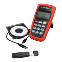
To install the USB driver, connect the meter to your PC using a USB cable. A dialogue box will automatically appear. Select "Install USB [for WINDOWS7_VISTA_XP_2000]" to proceed with the installation.

PC Software Installation:

Insert the provided disk into your PC's disk drive. A dialogue box should appear automatically. If it doesn't, manually execute "autorun.exe". The software installation guidance window will then appear, offering several options:

  • Install USB driver (for WINDOWS 7_VISTA_XP_2000): This option is for installing the USB driver.
  • Single Meter [Wireless & Cable]: Installs PC software for a single meter configuration.
  • Multi Meter [Wireless & Cable]: Installs PC software for a multi-meter configuration.
  • Instruction Manual: Provides access to the operation instruction manual.
  • Exit: Closes the installation program.

After selecting the appropriate installation option, the destination directory window will appear. You can choose the primary installation directory for the software. All software will be installed in the specified locations. You can browse to select different directories if needed.

Checking Connection Port:

To check the connection port, navigate to "Start" > "Control Panel" > "Performance and Maintenance". Then, select "System" and go to the "Hardware" tab, then "Device Manager". In the Device Manager, under "Ports (COM & LPT)", you will see the port number automatically assigned by the system (e.g., USB Serial Port (COM5)). This port number may be needed for manual connection. You can change it if necessary. After confirming, click "Continue" and then "Finish" in the FTDI Uninstaller window.

Uninstallation of USB Driver:

To uninstall the USB driver, go to "Start" > "Settings" > "Control Panel" > "Add or Remove Programs". Select "FTDI USB Serial Converter Drivers" and click "Change/Remove". The uninstallation process will then begin, deleting registry entries and files. Click "Finish" to exit once complete.

Description of "Single Meter" PC Software:

When the PC software for a single meter is launched, a "Welcome" window will appear. For first-time use, a communication port setup dialogue box will automatically open.

  • Auto connection: Click the "AUTO" button to let the system automatically select the communication port.
  • Manual connection: Select the COM port and baud rate manually. For wireless mode, select 57600 bps; for USB mode, refer to the operation manual. If you check "Do not show this window automatically", this dialogue box will only appear when called from the Setup menu.

After setting up the communication port, the main display window will appear.

  • File Menu:
    • About: Displays manufacturer information.
    • Exit: Exits the program.
  • Setup Options:
    • Environment selection settings: Refer to section 6.2 for details.
    • Communication port: Checks, searches, and sets communication port settings, showing the current port in use.
  • Log Setup:
    • Log Interval: Sets the meter log interval (default 1 sec).
    • Key Delay Time: Sets the key delay time (default 0 sec).
  • Display:
    • Graphic: Views real-time readings and curves.
    • Window setup: Refer to section 6.4 for details.
    • Relative: Sets and displays the difference between two channels.
  • Data Download: Downloads saved data from the meter (for save/data log function mode only).

Toolbar Explanations:

The toolbar provides quick access to various functions:

  • Communication port setup dialog box: Opens the communication port settings.
  • Set meter ID and CH (Only for wireless models): If the message "Meter not found on CH=00, ID=00" appears, click "Set" to connect. If the message "Meter not found on CH=00, D=00" appears, reset the ID and CH by turning off the meter, pressing and holding the wireless starting key (>2S) and power "on/off" key for longer than five seconds until "00" is displayed, then turning on wireless function by pressing the wireless starting key (>2S), and finally clicking "Relink".
    • Note: If multiple wireless transceivers are in the same location, assign different dongle IDs and maintain a distance of more than 30 cm (12 inches) between dongles.

Main Display Window:

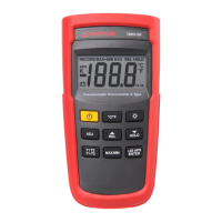
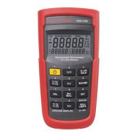
The left-hand side shows the reading of each channel with its unit. When using a thermocouple, the type is displayed in the upper-left corner. The right-hand side shows MAX, MIN, range (MAX-MIN), and AVG values, along with the times of maximum and minimum occurrences.

  • Hold: Holds the current reading.
  • Clean: Resets the reading and time of MAX, MIN, and AVG.
  • Hi/Lo: Activates out-of-limit alarms. Hi/Lo limit values are set in section 6.

Environment Selection Settings Dialogue Box:

This box allows you to configure various settings:

  • Time setting: Only available for meters with time setting function. Click "SET" to synchronize the meter's clock with the PC's time.
  • Dongle ID setting: Only available for meters with wireless function.
  • Sound of Hi/Lo limit setting: Click the data folder icon to select a sound effect (WAVE format only) for time-out and Hi/Lo alarms.
  • Hi/Lo limit setting:
    1. Setting the Limits: Audio alarms will activate when measurements are out of limits.
    2. Background color: The background color of each channel can be selected.
    • Stop Logging When Battery is Low: Enables or disables the function that stops data logging when the battery is low.
  • Relative dialog box (A-B / B-A): Displays the difference between two channels.

Graphic Dialogue Box:

  • Interval setting: Sets the logging interval (e.g., 1 sec).
  • Y scale setting:
    • Auto: Automatically sets the Y scale based on PC settings.
    • Turning off auto mode freezes the Y scale at that moment.
  • Data area: Displays the last ten measurements, including Date/Time, CH1, and CH2 readings.
  • CH1/CH2 Setting: Click "Setup" to turn on or off CH1 and CH2 and select their background colors.
  • Start data logger (Record): Click this button to open the "Log Setup" window.
    • File Name: Defines the name of the file for logged data (default is current time: YYYYMMDDHHMMSS).
    • File type: Can be saved as *.csv or *.xls.
    • User name: The user's name.
    • Path: The saved path.
    • Description: Information added by the user.
    • Click "OK" to start recording.
  • Stop data logger (Stop): Click to stop data logging and save the data.
  • Return to the main window after data logging ended: Go to "File" > "Exit".

Export Data:

To export data stored in the meter to the PC (only available for save/data log function), click the "Data download dialog box" icon.

  • Export options: You can choose to use the default name or save all groups. Select the file name, file type (Microsoft Excel *.xls), user name, group number, path, and description.

Received Signal Strength Indication (RSSI):

This feature is only available for meters with wireless function.

  • RSSI >= 60: Signal is better (green range).
  • 60 <= RSSI <= 50: Signal is good (yellow range).
  • RSSI <= 50: Signal is weak (red range).
  • Suggestions for weak signal: Change the location and orientation of the dongle (vertical to the ground is best) and the meter.

Low Battery Warning:

If a low battery warning appears, change the batteries as soon as possible.

Introduction of Main Display:

The left-hand side of the main display shows the reading of each channel with its unit. If a thermocouple is used, its type is shown in the upper-left corner. The right-hand side displays MAX, MIN, range (MAX-MIN), and AVG values, along with the times of maximum and minimum occurrences.

  • Hold: Holds the current reading.
  • Clean: Resets the reading and time of MAX, MIN, and AVG.
  • Hi/Lo: Activates out-of-limit alarms. Hi/Lo limit values are set in section 6.

User Linear Operation:

  • New: Creates a new blank file based on the default template.
  • Project:
    • Open: Opens an existing project file.
    • Save: Saves the active file with its current file name, location, and format.
    • Edit: Edits data.
    • Add: Adds data.
  • Add Item: Allows you to add new items, such as temperature or resistance.
  • Delete: Deletes data.
  • Calculate: Calculates polynomial values.
  • Order: Sets the order of the polynomial (e.g., 2).
  • Load to meter: Downloads user linear data to the meter.

Wireless Features:

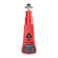
The device operates within specified frequency ranges (910-920MHz and 868.1-868.5MHz) with low current consumption (less than 1mA) and a transmission distance of 25M line-of-sight without magnetic interference.

FCC Compliance:

This device complies with Part 15 of the FCC Rules, meaning it must accept any interference received and not cause harmful interference. If interference occurs, measures such as reorienting the antenna, increasing separation from other equipment, or connecting to a different circuit may be necessary. Shielded interface cables must be used. Any unauthorized changes or modifications could void the user's authority to operate the equipment.

Description of Multi-Meter PC Software:

For multi-meter PC software, insert the dongle after software installation. Insert the dongle into a PC/USB port. The system will detect the dongle and install the driver.

Wireless Multi-Linking Version Instruction:

  1. Insert the USB dongle into the PC's USB slot.
  2. Start the PC software.

PS Software Description:

  1. Enter the start page.
  2. "New": Starts a new project (first use).
    • The system will search for a free channel.
    • Wizard configuration: Follow the step-by-step wizard.
    • Note: Add wireless instruments (ID/CH) one by one to the system to avoid working channel collision.
  3. "Load": Operates only with saved projects.
    • The system will load previous "ID/COM" from the saved file. Select the saved file.
  4. "Start key": Activates connection, displaying real-time measuring values. Add channels and display measuring values on the chart.
  5. Record data: Starts recording channel's data and measuring values into a .txt file.
  6. Save previous "ID/COM" to .ini file: Saves the current configuration.
  7. Magnify display dialogue: For easy and clear monitoring of channels and data.
  8. Dropdown menu:
    • Clear All: Clears the list and chart.
    • Setup: Sets Hi & Lo setting values to blink when they are exceeded.
    • About: Displays manufacturer information.
  9. Default File Save at: C:\800_Multi\record. The default file name is the current time (YYYYMMDDHHMMSS_ID_File Member).

Function Row:

  • Comport Find: Initiates a search for available COM ports.
  • Start recording data: Begins recording data.
  • Start execution key: Executes a function.
  • Enlarge display icons: Increases the size of display icons.
  • Auto Comport Find:
    • Comport connection: Indicates a successful COM port connection.
    • Comport connection fail: Indicates a failed COM port connection.

Recording Channel's Data:

Starts recording channel's data and measuring values into a .txt file. The default file save location is C:\800_Multi\record, and the file name is the current time (YYYYMMDDHHMMSS_ID_File Member).

"Start key" to Activate Connection:

  • Real-time measuring values display dialogue: Adds channels and displays measuring values on the chart.
  • Connection status dialogue: Displays the connection status of each meter.
    • Signal strength RSSI >= 60: Good (green area).
    • Signal strength 60 >= RSSI >= 50: Normal (yellow area).
    • Signal strength RSSI <= 50: Not good (red area).
    • Suggestions for weak signal: Refer to the previous section on RSSI.

Magnify Display Dialogue:

For easy and clear monitoring of channels and data.

  • Clear All: Clears the list and chart to empty.
  • Setup: Sets Hi & Lo setting values to blink when they are over the set values.
  • About: Displays manufacturer information.

Y-axis Setting for Each Channel:

  • Precision: Y-axis resolution setting.
  • AUTO Y Scale ON/OFF: Selects auto-scale.

FAQ:

  • Dongle not found: If the dongle is not found, reconnect it or check the USB port status (refer to page 2, step 2).
  • Working CH occupied: If a "Working CH occupied" message appears, exit the software and restart the connection.
  • Getting Meter ID Mark error: Before playing, ensure the meter is powered on. If an error message appears, the meter might be off or not connected.
  • ID NO. not displayed: If the ID number is not displayed when connecting to a USB cable, check the COM port status (page 2). If the COM port is COM3 or COM10, change it to another COM port.
  • Data display sequence: The data is displayed by connecting sequence, not by ID number. The first connected instrument might not be ID 01.

Comport Confirmation Procedure:

  1. Confirm port assignment: Verify if the PC's port (COM&LPT1) is assigned to the meter. It might be a different Comport than COM6.
  2. Change port (if necessary): If the port needs to be changed, click on "Properties" of the red frame in Device Manager.
  3. Choose Comport: Select a Comport other than COM10, COM3, and any COM port without "IN USE".
  4. Complete and re-scan: Complete the steps and re-scan the device. Then, open the software to perform Auto-Connection.

Amprobe TMD Series Specifications

General IconGeneral
TypeThermometer
Input TypeThermocouple (Type K)
DisplayLCD
Resolution0.1°C or 0.1°F
Accuracy±1.0°C or ±1.8°F
Sensor TypeThermocouple (Type K)
Operating Conditions0°C to 50°C (32°F to 122°F)
Storage Conditions-20°C to 60°C (-4°F to 140°F)

Related product manuals