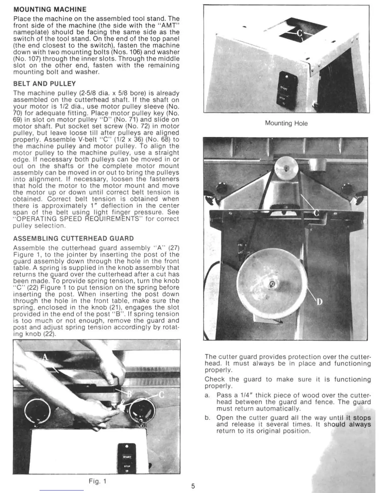
MOUNTIN
G
MACHINE
Place the machine on the assembled tool stand. The
front
side
of
the
machine
(the
side
with
the
"
AMT"
nameplate)
should
be facing the same side as the
switch
of
the
tool
stand.
On
the
end
of
the
top
panel
(the
end
closest
to
the switch), fasten the machine
down
with
two
mounting
bolts
(Nos. 106)
and
washer
(No. 107)
through
the
inner
slots.
Through
the
middle
slot
on
the
other
e
nd
, fasten
with
the
remaining
mounti
ng
bolt
and washer.
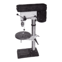
BELT
AND
PUllEY
The
machine
pulley
(2·5f8 dia. x
518
bore)
is
already
assembled
on
the
cutterhead
shaft.
If
the
shaft
on
your
mol
or is 1'2 dia
.,
use motor pulley sleeve (No.
70)
for
adequate
fitling
. Place
molor
pulley
key (No.
69)
in
slot
on
motor
pulley
" 0 " (No. 71)
and
slide
on
motor
shaft
. Put
socket
set
screw
(No.
72)
in
motor
pulley. but leave
loose
till
after
pulleys
are atigned
properly.
Assemble
V-belt "C" (1/2 x
36)
(No.
68)
to
the
machine
pulley and
motor
pulley. To align the
motor
pulley
to the
machine
pulley, use a straight
edge.
If necessary
both
pulleys
can be moved in
or
out
on the
shafts
or
the
complete
molar
mount
assembly
can be moved in
or
out
to bring the putleys
into
alignment.
If
necessary, loosen the fasteners
that
hold
the
motor
to
the
motor
mount
and move
the
motor
up
or
down
until
correct
belt tension is
obtained. Correct
belt
tension
is
obtained
when
there is
approximately
1"
deflection
in the center
span
of
the
belt
using
light
finger
pressure. See
"O
PERATING SPEED REQUIREMENTS" for
co
rrect
pulley
selection.
ASSEMBLING
CUTTERHEAD GUARD
Assemble
the cuUerhead l;Iuard
assembly
" A"
(27)
Figure 1, to the
jointer
by Inserting the post
of
the
guard
assembly
down
through
the hole in the front
tabl
e.
A spring is
supplied
in the knob
assembly
that
returns the guard over the c
utt
erhead
after
a cut has
been made.
To
provide
spring
tension, turn the knob
"C"
(22)
Figure 1 to put
tension
on the spring before
inserting
the post. When
inserting
the post down
through
the
hole
in the front table, make sure the
spring,
enclosed
in the knob (21), engages the
slot
provided in
the
end
of
the post
"8".
If
spring
tension
is too
much
or
not
enough, remove the guard and
post and
adjust
spring
tension
accordingly
by rotat-
ing
knob
(22).
Fig. 1
5
Mounting Hole
The
cutter
guard provides
protection
over the cutter-
head. It
must
always be in place and
functioning
properly.
Check the guard to make sure
it
is
functioning
properly.
a.
Pass a 1/4"
thick
piece
of
wood over the cutter-
head between the guard and fence. The guard
must
return automaticalty.
b.
Open the
cutter
guard all the way
until
it
stops
and release it several times. It should
always
re
turn to
its
original
position,