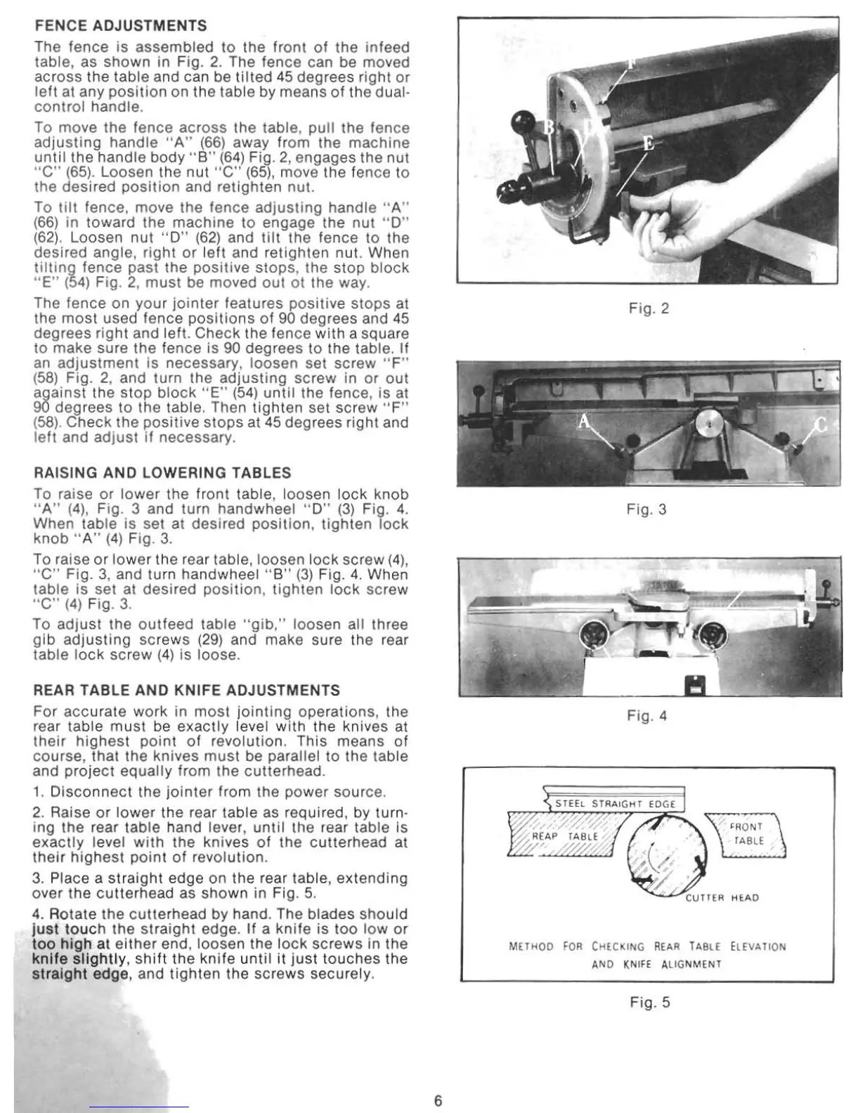
FENCE ADJUSTMENTS
The fence is
assembled
to the front
of
the
infeed
table, as shown in Fig.
2.
The fence can be moved
across the table and can be
tilted
45 degrees
right
or
left
al any
position
on the table by means
of
the
dual-
control
handle
.
To
move
the fence
across
the table,
pull
the fence
adjusting
handle
" A" (66)
away
from
the
machine
until the handle body
"S
"
(64)
Fig.
2,
engages the nut
" C"
(65).
Loosen the nut "e"
(65),
move the fence to
the
desired
position
and
retighten
nut.
To
lilt
fence. move the fence ad
justing
handle " A"
(66)
in toward the
machine
to engage the
nul
"
0"
(62).
Loosen
nut
"0"
(62) and tilt the fence to the
desired
angle,
right
or
left
and retighten nut. When
tilt
ing fence past the
positive
stops
, the Slop
block
HE" (54) Fig. 2,
must
be moved
oul
at
the way.
The fence on your
jointer
features
positive
stops
at
the
most
used fence
positions
of
90 degrees and
45
degrees
right
and left. Check the fence
with
a squa
re
to
make
sure the fence is 90 degrees to the table. If
an
adjustment
is necessary, loosen set screw " F"
(58) Fig. 2, and turn the
adjusting
screw
in
or
out
against the
stop
block
"E"
(54)
until
the fence, is at
90
degrees to the table. Then
tighten
set screw "
F"
(
58)
, Check
the
positive
stops
at
45
degrees right and
left
and ad
just
if
necessary.
RAISING AND LOWERING TABLES
To
raise
or
lower
the front table, loosen
lock
knob
"
A"
(4)
, Fig. 3 and turn handwheel "
0"
(3)
Fig.
4.
When table is set at desired pOSition,
tighten
lock
knob
" A"
(4)
Fig.
3.
To raise
or
lower
the rear table, loosen
lock
screw
(4),
"
C"
Fig. 3, and turn handwheel
"8"
(3)
Fig.
4.
When
table
is
set at desired
position
,
tighten
lock
screw
" C"
(4)
Fig. 3.
To
adjust
the
outfeed
table "
gib
,"
loosen all three
gib
adj
usting
screws (29) and make sure the rear
table
lock
screw
(4)
is
loose
.
REAR TABLE AND
KNIFE ADJUSTMENTS
For accurate
work
in
most
jointing
operations, the
rear table
must
be
exactly
level
with
the knives at
their
highest
point
of
revolution.
This
means
of
course, that the knives
must
be parallel to the table
and
project
equally from the cutterhead.
1.
Disconnect
the
jointer
from the
power
source.
2. Raise
or
lower
the rear table as required, by turn·
ing
the rear table hand lever,
unt
il the rear table is
exactly
levet
with
the knives
of
the c
ulterh
ead at
their
highest
point
of
revolution.
3.
Place a
straight
edge on the rear table,
extending
over
the
culterhead
as
shown
in Fig.
5.
4.
Rotate
the
cutterhead
by hand. The blades
should
Just
touch
the st
ra
ight edge.
If
a
knife
is too
low
or
too
high
at
either
end, loosen the
lock
screws
in the
knife
slightly
,
shift
the
knife
until
it
jus
t
touches
the
straight
edge, and
tighten
the screws securely.
6
Fig
. 2
Fig. 3
Fig. 4
SHEl
STRA.IGHT f OC,(
METHOD
FOR
CHECKING
REA.R
TA.B
LE
ELEVA.HON
A.ND
KNIfE
A.
lIGNMENT
Fig. 5