Installing Tabletop (MXT) Panels
22
Modero S Series Touch Panels - Installation & Hardware Reference Manual
Installing Tabletop (MXT) Panels
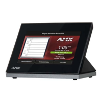
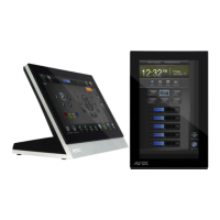
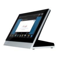
MST-1001/701/431
Detailed specifications drawings for the MST-1001 are available to download from www.amx.com.
Detailed specifications drawings for the MST-701 are available to download from www.amx.com.
Detailed specifications drawings for the MST-431 are available to download from www.amx.com.
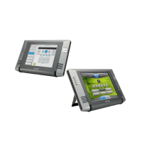
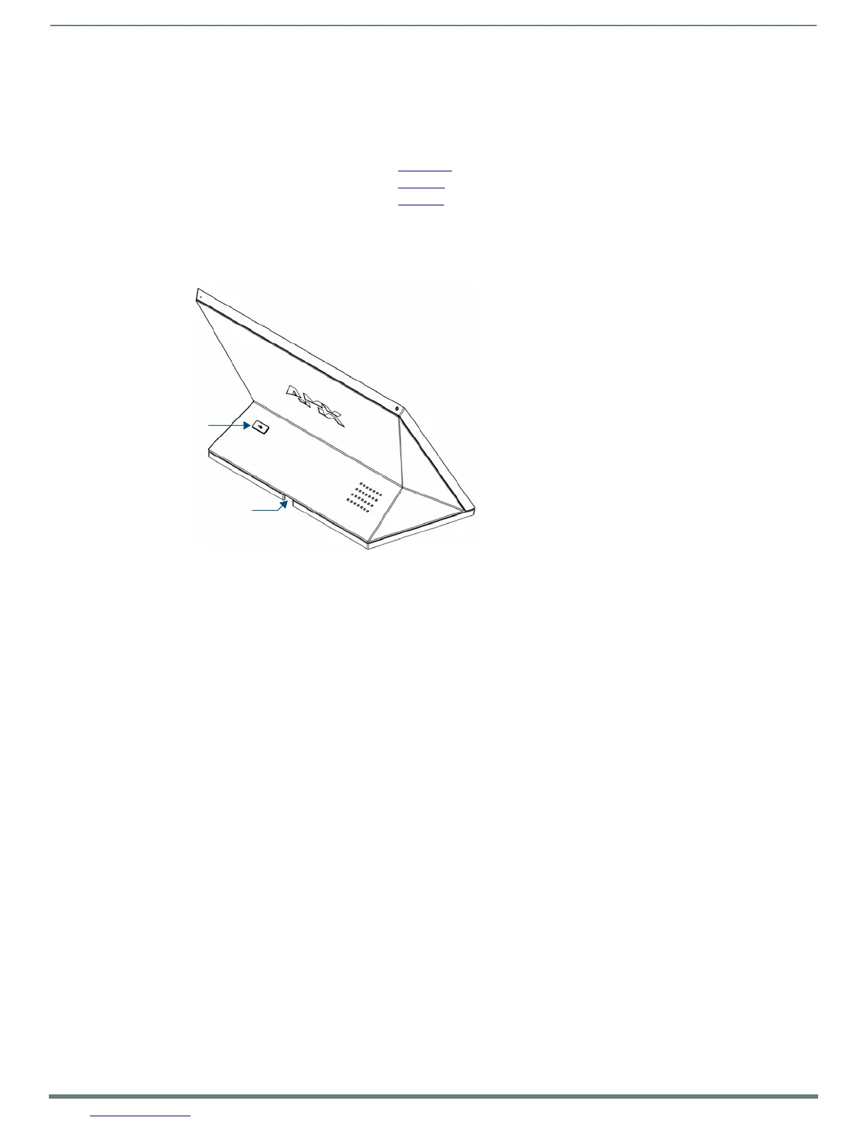
Connector Locations
USB peripherals (mouse, keyboard, etc.) may be connected to the USB port on the rear of the device. Updates to the device’s
firmware can also made via the USB port.
Note that FIG. 12 shows a MST-1001, but the connector locations are similar for all MST panels:
Power via Power Over Ethernet
Power for the MST-1001 is supplied via Power Over Ethernet (PoE), utilizing an AMX-certified, capacitive touch-compliant PoE
injector such as the PS-POE-AT-TC High Power PoE Injector (FG423-83) or other approved AMX PoE power source.
The incoming Ethernet cable should be connected to the RJ45 port on the panel.
FIG. 12
MST-1001 Connector Location
 Loading...