Upgrading Firmware
73
MVP-5200i Modero® ViewPoint® Touch Panel with Intercom - Instruction Manual
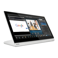
3. Click on the NetLinx Master radio button from the Platform Selection section.
4. Click on the Virtual Master radio box from the Transport Connection Option section to configure the PC to communicate
directly with a panel. Everything else, such as the Authentication, is disabled because this connection is not going through the
Master’s UI.
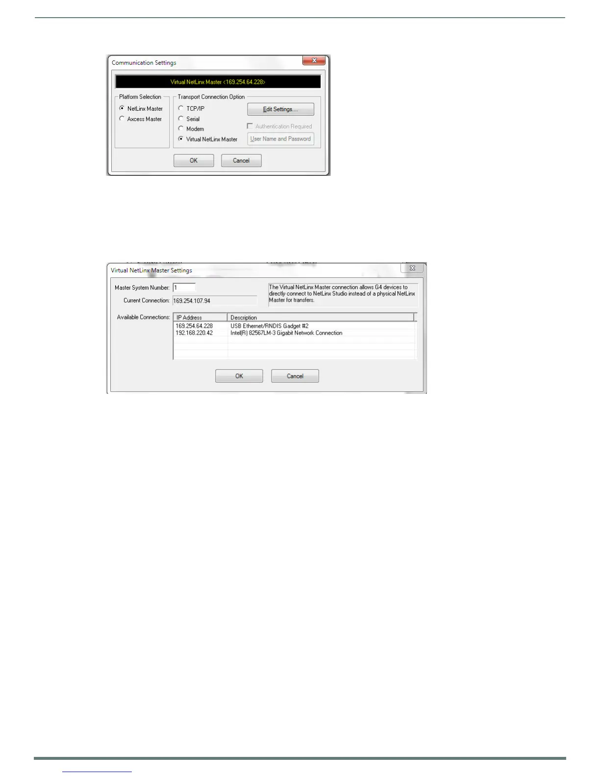
5. Click the Edit Settings button on the Communications Settings dialog to open the Virtual NetLinx Master Settings dialog
(FIG. 75).
6. Within this dialog, enter the Master System number. The default is 1.
7. In the Available Connections section, click on the IP address for the touch panel to select it.
8. In the Virtual NetLinx Master Settings dialog, click OK to close the box.
9. In the Communications Settings dialog, click OK to close the box.
10. In the Master Communications Settings dialog, click OK to save your settings and return to the main NetLinx Studio
application.
11. Click the OnLine Tree tab in the Workspace window to view the devices on the Virtual System. The default System value is 1.
12. Right-click on the Empty Device Tree/System entry and select Refresh System to re-populate the list.
NOTE: The panel will not appear as a device below the virtual system number, in the Online Tree tab, until both the system
number used in step 14 for the Virtual NetLinx Master is entered into the Master Connection section of the System Settings page
and the panel is restarted.
13. The OnLine Tree should now display the connection to the device. The Connection Status Icon on the device may take up to
five seconds to register the connection.
Step 3: Conf irm and Upgrade the f irmware via the USB port
Use the CC-USB Type-A to Mini-B 5-wire programming cable to provide communication between the mini-USB Program port on the
touch panel and the PC. This method of communication is used to transfer firmware Kit files and TPD4 touch panel files.
NOTE: A mini-USB connection is only detected after it is installed onto an active panel.
1. Verify that the direct USB connection (Type-A on the panel to mini-USB on the panel) is configured properly, using the steps
outlined in the previous two sections.
2. With the panel already configured for USB communication and the Virtual Master setup within NetLinx Studio, refresh the
Online Tree pane.
3. After the Communication Verification dialog window verifies active communication between the Virtual Master and the panel,
click the OnLine Tree tab in the Workspace window (FIG. 76) to view the devices on the Virtual System. The default System
value is 1.
4. Right-click on the System entry (FIG. 76) and select Refresh System to re-populate the list. Verify the panel appears in the
OnLine Tree tab of the Workspace window.
FIG. 74
Communications Settings dialog
FIG. 75 Virtual NetLinx Master Settings

 Loading...