www.analog.com
Analog Devices
│
22
MAX30001 Evaluation System Evaluates: MAX30001
MAX30002
BioZ Measurement
Additionally, the EV kit includes a 100Ω resistor to verify
the BioZ conguration. Attach shunts on RP and RN to
connect the resistor to the BioZ inputs and shunts on
DP_BP and DN_BN to route the drive signal to the BioZ
channel. Figure 19 illustrates these connections.
Refer to the MAX30001 data sheet for details on conguring
a BioZ measurement. Note that the default setting of the
current generator is FMSTR/64 (about 500Hz) and the
BioZ channel has an internal high-pass lter with a default
1kHz cuto frequency. In order to correctly measure the
100Ω resistor, bypass or lower the lter cuto frequency
or increase the current generator frequency.
Pace Detection
To enable pace detection, the ECGN and ECGP lines must
be connected to BIN and BIP by shunting EN_BN and
EP_BP, then conguring the device registers as described
in the IC datasheet. Refer to Figure 20 for a jumper
conguration to measure ECG with pace detection.
Alternatively, EP_BP and EN_BN can be left open and
J_BIP and J_BIN shunted. This measures pace directly
on the BIP and BIN inputs and allows another signal to be
measured on the ECG channel. In this conguration, the
measured pace signal may not correspond to the ECG
measurement.
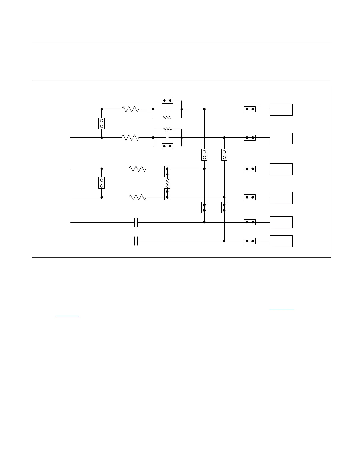
Figure 18. Default Measurement Channel Jumper Configurations
EP_EN
0Ω
BP_BN
0Ω
EN_UNBAL
EP_UNBAL
RP
RN
EP_BP EN_BN
J_ECGP
J_DRVP
J_ECGN
J_BIP
J_BIN
J_DRVN
47nF
47nF
DRVN
DRVP
BIN
BIP
ECGN
ECGP
DRVN
DRVP
BIN
BIP
ECGN
ECGP
100Ω
DP_BP DN_BN
0Ω
0Ω
 Loading...