Do you have a question about the Anden A710V1 and is the answer not in the manual?
Details minimum clearances and airflow considerations for optimal unit placement.
Specifies recommended spacing for efficient operation and maintenance.
Covers hanging methods, rod usage, vibration isolators, nuts, and washers.
Explains how to ensure the unit is properly leveled for safe operation.
Details the proper setup for drain lines, including traps, pipe slope, and support.
Illustrates wiring connections for the Model A77 control unit and remote sensor.
Describes the power-up sequence and how the unit adjusts humidity settings.
Lists common error codes, their failure modes, and troubleshooting advice.
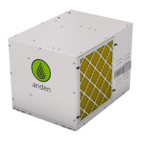
The Anden Model A710V1/V3 Dehumidifier is designed to control humidity levels in a given space, ensuring optimal environmental conditions. This quick start guide provides essential information for installation, operation, and basic troubleshooting.
The primary function of the Anden Model A710V1/V3 Dehumidifier is to remove excess moisture from the air. It operates by drawing in humid air, cooling it to condense the moisture, and then expelling drier air back into the environment. The condensed water is collected and drained away. The device is designed to work in conjunction with an external control system, such as the Model A77, to monitor and regulate humidity levels automatically. When the measured relative humidity (RH) rises above a user-defined set point, the dehumidifier activates to reduce the moisture content. It will continue to operate until the RH drops below the set point, typically by a 3% margin, ensuring efficient and consistent humidity control.
Placement and Installation: Proper placement is crucial for the dehumidifier's performance. It requires a minimum of 18 inches of clearance around the inlet and outlet to ensure adequate airflow. The unit can be placed on a flat surface or suspended from a ceiling using threaded rods. When hanging, it is recommended to use vibration isolators to minimize noise and vibration. The installation process involves connecting the drain line, which must maintain a constant downward slope and should not be double-trapped. A P-trap is included and should be primed upon installation. A vacuum break is recommended, especially when using a condensate pump or connecting multiple drain lines, to prevent microbial growth and ensure proper drainage. The electrical service panel should also have 18 inches of clearance.
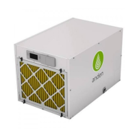
Control and Operation: The dehumidifier is typically controlled by an external device, such as the Anden Model A77 control. To initiate operation, the unit's power switch must be turned ON. The on-board control screen will initially display "OFF." To enable the unit, the UP or DOWN button on the control is pressed until "ENABLED" appears. The MODE button is used to navigate through settings, and holding it for 3 seconds allows access to the Installer Set-up Menu. Once enabled, the Model A77 control displays the measured RH and "ON." Users can adjust the desired humidity setting using the UP or DOWN buttons on the Model A77. When the RH exceeds the set point, the dehumidifier automatically turns on, indicated by "DEHUMIDIFYING" on the dehumidifier control display and a blinking "ON" on the Model A77. The unit will turn off once the RH drops 3% below the set point. There is an initial 3-minute delay at power-up before the compressor engages.
Drain Connection: The drain connection is a critical aspect of the installation. The unit includes a 3/4" pipe tee and a P-trap. Hard PVC pipe (not included) is typically used for the drain line. It is essential that the drain line maintains a constant downward slope to ensure proper water flow and prevent pooling, which could lead to microbial growth. Supporting the drain lines is also important to prevent dips or sags. The end of the drain line should not be submerged in water. An optional vacuum break can be installed, particularly when connecting to a condensate pump or multiple drain lines.
Wiring: The dehumidifier requires electrical wiring according to the provided diagrams. The Model A77 control connects to the dehumidifier via specific terminals for remote sensing and control signals. It is important to ensure all wiring is done in accordance with local electrical codes and the provided instructions. The Model A77 control should be mounted at canopy height and shielded from direct light. It should not be mounted in the direct path of the dehumidifier's outlet air to ensure accurate readings.
Troubleshooting Error Codes: The dehumidifier is equipped with a system to display error codes, which are located on the back of the wire access cover. These codes help in diagnosing potential issues. For example:
In case of an error, users are advised to consult the Installation Instructions for detailed troubleshooting steps. For further assistance, Technical Support is available during business hours. It is recommended to contact Technical Support before attempting to replace any components or the unit itself.
General Maintenance: While specific maintenance schedules are not detailed in this quick start guide, general best practices for dehumidifiers include regular inspection of the drain line to ensure it is clear and free of obstructions. Keeping the area around the dehumidifier clear of debris and ensuring proper airflow will contribute to its efficient operation and longevity. The control unit should also be kept clean and free from obstructions to ensure accurate readings and proper functionality.
| Model | A710V1 |
|---|---|
| Refrigerant | R410A |
| Power Supply | 115V, 60Hz |
| Auto Restart | Yes |
| Auto Defrost | Yes |
| Dehumidification Capacity | 70 Pints/Day |
| Continuous Drainage | Yes |