This document is a user manual for a 9999 counts true RMS auto-ranging digital multimeter. It provides comprehensive information on the device's functions, usage, and maintenance.
Function Description
The multimeter is designed to perform a wide range of electrical measurements. It can measure AC/DC voltage, AC/DC current, resistance, capacitance, frequency, and duty cycle. Additionally, it features diode and continuity tests, a non-contact voltage (NCV) test, a V.F.C (Variable Frequency Drive) test, and a square wave output function. The device is capable of measuring both sinusoidal and non-sinusoidal AC waveforms accurately, thanks to its True RMS capability.
Usage Features
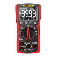
The multimeter features an LCD display that shows primary and secondary measurements, along with various indicators for different modes and functions.
Display Indicators:
- AUTO: Indicates auto-ranging mode, where the product automatically selects the range with the best resolution.
- MANU: Indicates manual range mode, allowing the user to select the range.
- F: Capacitance test (Farad).
- Δ: Relative mode.
- →|←: Diode test.
- •))): Continuity test.
- %: Duty cycle test.
- -8.8.8.8 (Secondary): Secondary measurements display.
- AC: Alternating current.
- DC: Direct current.
- Hz: Frequency test (Hertz).
- °C: Temperature test (Celsius).
- °F: Temperature test (Fahrenheit).
- Analog bar graph: Visual representation of the measured value.
- Ω: Resistance test (Ohm).
- A: Current test (Ampere).
- V: Voltage test (Volt).
- -8.8.8.8 (Primary): Primary measurement display.
- T-RMS: Indicates that the product measures both sinusoidal and non-sinusoidal AC waveforms accurately.
- Battery icon: Low battery indicator, prompting battery replacement.
- Minus sign: Negative readings.
- HOLD: Display freezes the present reading.
- V.F.C: Frequency converter test.
- MAX: Displays the maximum value measured.
- MIN: Displays the minimum value measured.
- nkMmm: Measurement units.
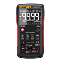
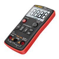
Function Buttons:
The device is equipped with several function buttons:
- SELECT/V.F.C: A short press switches among different functions within a rotary switch position. A long press enters the V.F.C function.
- RANGE/REL: A short press changes the measurement range. A long press (more than 2 seconds) activates the relative mode, storing the current reading as a reference and zeroing the display for subsequent readings. Another long press exits this mode.
- MAX/MIN: This button switches between maximum and minimum value display modes. A long press (2 seconds) exits the MAX/MIN mode.
- HOLD/Flashlight: A single press holds the current reading on the display. Pressing it again resumes normal operation. A long press (beyond 2 seconds) turns the flashlight on or off.
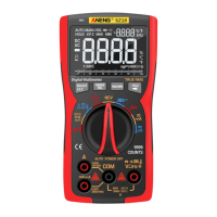
Rotary Button:
The main rotary switch selects the primary measurement function.
- OFF: Turns off the product. The device has an auto-power-off feature that activates after 15 minutes of inactivity. A built-in beeper sounds 5 times one minute before auto-power-off. To restart, press the SELECT button or turn the rotary switch to OFF and then to the desired position. To disable auto-power-off, hold down the SELECT button while turning on the product; five beeps will confirm successful disabling.
- V.F.C / %Hz V: For AC/DC voltage, frequency, and duty cycle measurements.
- %Hz mV: For AC/DC millivolt, frequency, duty cycle, and temperature measurements.
- Ω / Diode / Continuity / Capacitance: For resistance, diode test, continuity test, and capacitance measurements.
- NCV: For non-contact voltage detection.
- Square Wave Output: For generating square wave signals at various frequencies.
- mA: For DC and AC milliampere current measurements.
- μA: For DC and AC microampere current measurements.
- A: For DC and AC ampere current measurements.
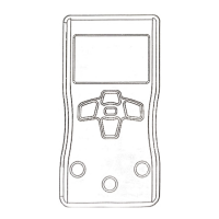
Input Terminals:
- A: Input terminal for AC/DC current measurements up to 9.999A.
- μA/mA: Input terminal for AC/DC current measurements up to 99.99mA.
- COM: Common (return) terminal for all measurements.
- VΩHz→|←•)))T-RMS: Input terminal for measurements of diode, continuity, square wave, temperature, AC/DC voltage, resistance, frequency, and capacitance.
Measurement Instructions:
- AC/DC Voltage: Connect the black lead to COM and the red lead to VΩHz→|←•)))T-RMS. Turn the rotary switch to the appropriate voltage range (mV or V). Use SELECT for AC voltage.
- AC/DC Current: Connect the black lead to COM and the red lead to A or μA/mA. Turn the rotary switch to the desired current range (μA, mA, or A). Break the circuit, connect the leads across the break, and apply power.
- Resistance: Connect the black lead to COM and the red lead to VΩHz→|←•)))T-RMS. Turn the rotary switch to Ω and press SELECT for resistance mode. Disconnect circuit power and discharge capacitors before testing.
- Diodes and Continuity: Connect the black lead to COM and the red lead to VΩHz→|←•)))T-RMS. Turn the rotary switch to Ω and press SELECT for continuity/diode mode. For diodes, connect the red probe to the anode and the black probe to the cathode. For continuity, touch probes to circuit points; a beep indicates a short circuit.
- Capacitance: Connect the black lead to COM and the red lead to VΩHz→|←•)))T-RMS. Turn the rotary switch to Ω and press SELECT for capacitance mode. Disconnect circuit power and discharge capacitors before testing.
- Frequency and Duty Cycle: Connect the black lead to COM and the red lead to VΩHz→|←•)))T-RMS. Turn the rotary switch to %Hz V (for ≥10V, 1-100KHz) or %Hz mV (for ≤10V, 1-5MHz). Press SELECT. For frequencies between 100kHz and 5MHz, enter AC mV position, touch probes, then press SELECT again to show frequency and duty cycle.
- Temperature: Connect the black lead to COM and the red lead to VΩHz→|←•)))T-RMS. Turn the rotary switch to %Hz mV and press SELECT for temperature mode. The main display shows Celsius, and the vice display shows Fahrenheit.
- NCV: Turn the rotary switch to NCV. Hold the product and move it around; the beeper will sound when AC voltage is detected, with quicker beeps indicating stronger voltage.
- V.F.C Test: Connect the black lead to COM and the red lead to VΩHz→|←•)))T-RMS. Turn the rotary switch to V.F.C and long press SELECT. The screen will show voltage when leads are connected to the correct circuit.
- Square Wave Test: Connect the black lead to COM and the red lead to VΩHz→|←•)))T-RMS. Turn the rotary switch to the square wave symbol. The default output frequency is 50Hz; press the SEL button to change it.
Safety Information:
The manual emphasizes several safety precautions to prevent electrical shock, fire, or personal injury:
- Always read safety information before use.
- Use the product only as specified.
- Examine the case for cracks or missing plastic and check insulation around terminals.
- Ensure measurements are made with correct input terminals, functions, and within the allowable range.
- Do not use in explosive gas, vapor, or damp/wet environments.
- Keep fingers behind finger guards on probes.
- Do not touch unused input terminals when connected to a live circuit.
- Disconnect test leads before changing modes.
- Exercise caution when measuring voltages exceeding 36V DC or 25V AC.
- "OL" indicates an out-of-range input.
- Replace batteries when the low battery indicator appears to ensure accurate readings.
- Do not make measurements if the battery door is not properly placed.
- Do not measure voltage or current exceeding specified extremes.
- Do not input voltage when measuring current or resistance.
- Disconnect circuit power and discharge all capacitors before testing resistance or diodes.
Maintenance Features
The manual outlines basic maintenance procedures for the multimeter. Beyond replacing batteries and fuses, users are advised not to attempt repairs unless qualified and possessing relevant calibration, performance test, and service instructions.
Cleaning:
- Wipe the product with a damp cloth and mild detergent.
- Avoid abrasives or solvents.
- Ensure no dirt or moisture in the terminals, as this can affect readings.
- Remove input signals before cleaning the product.
Battery Replacement:
- When the low battery indicator is shown, batteries need to be replaced.
- Remove test leads and turn off the product.
- Loosen the screw on the battery door and remove it.
- Replace used batteries with new ones of the same type. The device uses 3 AAA 1.5V batteries.
- Place the battery door back and fasten the screw.
Fuse Replacement:
- If a fuse is blown or not working properly, it must be replaced.
- Remove test leads and turn off the product.
- Loosen the four screws on the back cover and the screw on the battery door.
- Remove both the battery door and the back cover.
- Replace the fuse with a new fuse of the same type.
- Place the back cover and battery door back, then fasten the screws.