Do you have a question about the Aneng M118A and is the answer not in the manual?
Details general specifications like display mode, maximum display value, sampling rate, working environment, and physical dimensions.
Explains the automatic scanning test procedure for DC/AC voltage, including connection and range switching.
Details the resistance measurement process, including auto-ranging, buzzer function for low resistance, and on-line measurement precautions.
Outlines the procedure for performing diode forward voltage drop tests and continuity checks with buzzer indication.
Describes how to measure capacitance, including the need for discharging capacitors and the auto-ranging capability.
Covers the current testing function, emphasizing safety precautions for connecting in series and maximum current limits.
Explains how to use the Non-Contact Voltage (NCV) test function to detect AC voltage and signal intensity.
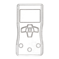
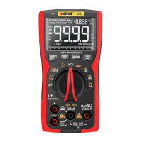
This document describes an Automatic Scanning Digital Multimeter, a pocket-sized instrument designed for a variety of electrical measurements. It features a 3 5/6 bit true effective value automatic scanning digital meter, capable of identifying and measuring input voltage, current, resistance, and other signals automatically. The multimeter is characterized by stable performance, high precision, and clear readings, making it suitable for factory use, educational purposes, and electronics enthusiasts.
The multimeter is primarily used for measuring DC and AC voltage, DC and AC current, resistance, diode and on-off tests, and capacitance. It incorporates an automatic scanning feature that identifies the type of signal being measured and adjusts its range accordingly.
For DC/AC voltage measurement (DCV/ACV), the device automatically scans and displays the voltage. When the voltage between the input ports "COM" and "V/Ω" is greater than 0.5 V, the meter compares the DC and AC components, takes the larger component signal, and then automatically switches the range based on the measured value. In environments with significant interference, the user can manually select DC or AC voltage measurement mode. It's crucial to ensure the input voltage does not exceed DC 600 V or AC 600 V to prevent damage. Special attention to safety is required when measuring voltages above 36 V to avoid electric shock. After measurements, the meter pens should be disconnected from the circuit.
Resistance measurement also begins with an automatic scan. If the resistance between the meter pens is less than 50 Ω, a continuous buzzer sound indicates the need for a fast buzzer measurement, which can be manually selected. If a closed-loop resistance is measured, the ends of the resistance must be discharged. Otherwise, if the voltage in the loop exceeds 0.6 V, the instrument may mistakenly enter voltage measurement mode. For low resistance measurements, users can short-circuit the meter pens to record a short-circuit value and subtract it from the measurement reading for accuracy. When measuring on-line resistance, all power supplies in the circuit must be turned off, and all capacitors discharged to ensure accuracy. The meter automatically switches the range based on the actual resistance value and displays it on the LCD.
For diode measurements, the device displays the positive pressure drop of the measured diode on the LCD. If the polarity of the diode in contact with the pens is reversed or the diode is open, the LCD will show "OL".
Capacitance measurements are also initiated via automatic scan. The meter automatically switches the range according to the capacitance value between the red and black meters and displays the specific value on the LCD. Before measuring capacitance, it is essential to fully discharge the capacitor to prevent the device from entering voltage measurement mode. When measuring capacitance with the 10 nF range, there might be a residual reading due to the meter's distributed capacitance; this value can be subtracted for a more accurate reading. For serious leakage or breakdown capacitance, or large capacitance values, the LCD may show unstable readings or take a few seconds to stabilize, which is considered normal.
Current Test Function (DC/AC A) requires the black watch pen to be inserted into the "COM" jack and the red watch pen into the "10 A" jack. If the input current between "COM" and "10 A" is greater than 20 mA, the meter displays the current value, prioritizing the larger AC or DC component. Before connecting the instrument in series to the circuit, the power in the circuit must be turned off. The maximum input current is 10 A; exceeding this can burn out the internal fuse. Each measurement should not exceed 10 seconds, as prolonged or excessive current can cause the instrument to heat up or be damaged. It is crucial not to connect the meter pen test pin parallel to any circuit when the red meter pen is in the "10 A" port, as this will damage the fuse and meter. After all current measurement operations, the power supply should be turned off, and the connection between the meter pen and the circuit disconnected. No more than 36V DC or 25V AC voltage should be entered between the 10A port and the COM port.
The multimeter also includes a Non-Contact Voltage (NCV) measurement function. By pressing the 'NCV' key, the instrument enters EF measurement mode. When the NCV test induction end is brought close to an AC voltage source, the buzzer will emit continuous sounds of varying frequencies, and the LCD will display different segments according to the signal strength.
The device is designed for ease of use, incorporating several features to enhance the user experience:
The manual emphasizes several points related to the safe and proper use of the multimeter, which indirectly contribute to its maintenance and longevity:
| Diode Test | Yes |
|---|---|
| Continuity | Yes |
| hFE Test | Yes |
| NCV | Yes |
| Data Hold | Yes |
| Backlight | Yes |
| DC Current | 0.1μA to 10A |
| AC Current | 0.1μA to 10A |
| Frequency | 0.1Hz to 10MHz |
| Temperature | -20°C to 1000°C |