Programming with SCPI 1-3 Remote Programming Setup and Interface
MS2090A PM PN: 10580-00445 Rev. C 1-3
Network Connection
Interface between the instrument and other devices on the network is via a category five (CAT-5) interface
cable connected to a network. This cable uses four twisted pairs of insulated copper wires terminated into an
RJ45 connector. CAT-5 cabling is capable of supporting frequencies up to 100 MHz and data transfer speeds up
to 1 Gbps, which accommodates 1000Base-T, 100Base-T, and 10Base-T networks. CAT-5 cables are based on
the EIA/TIA 568 Commercial Building Telecommunications Wiring Standard developed by the Electronics
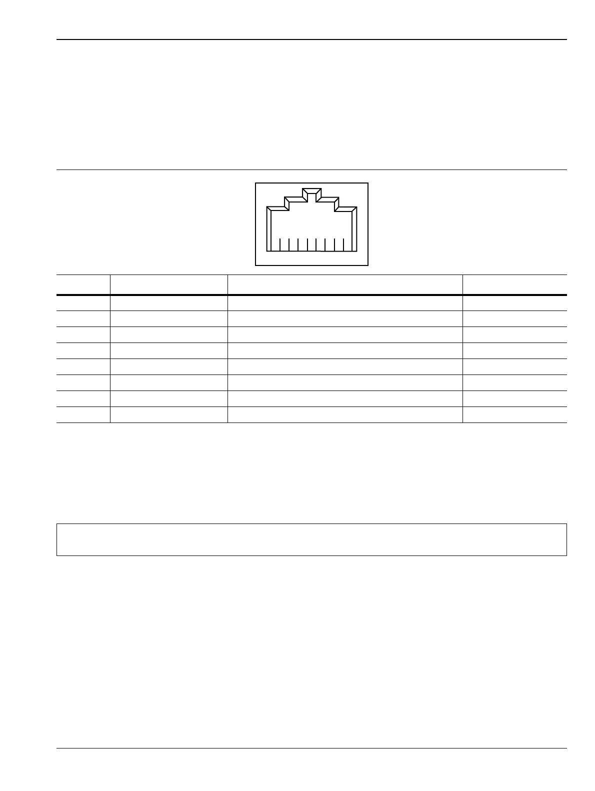
Industries Association. A pinout diagram is shown in Table 1-1.
Integrated into the RJ45 connector are two LEDs. The amber LED indicates the presence of LAN voltages (a
live LAN connection) while the green LED flashes to show that LAN traffic is present. The instrument IP
address and its HOSTNAME are set via the System menu (upper left corner) and accessing the ETHERNET or
WIFI settings menu.
TCP/IP connectivity requires setting up the parameters described at the beginning of this section. The
following is a brief overview of how to set up a general LAN connection on the MS2090A.
Table 1-1. 8-pin Ethernet RJ45 Connector Pinout Diagram
Pin Name Description Wire Color
1 TX+ Transmit data (> +3 volts) White/Orange
2 TX– Transmit data (< –3 volts) Orange
3 RX+ Receive data (> +3 volts) White/Green
4 – Not used (common mode termination) Blue
5 – Not used (common mode termination) White/Blue
6 RX– Receive data (< –3 volts) Green
7 – Not used (common mode termination) White/Brown
8 – Not used (common mode termination) Brown
Note
You may need to consult your network documentation or network administrator for assistance in
configuring your network setup.
ООО "Техэнком" Контрольно-измерительные приборы и оборудование www.tehencom.com
 Loading...


