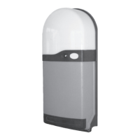
CourtesyLight
RS1
Control
Button
RedLED
Indicator
Figure3
Entera4digitpersonal
accesscodetooperate
yourdoor.
Weatherproofhighsecurity
unitwithkeyillumination
suitableforinstallation
outsidethegarage.
Ultrasecurekey
operationforyour
door.
Weatherproofhigh
securityunitwithblue
LEDindicatorsuitable
forinstallationoutside
thegarage
Tocontrolthedoor
fromanalternative
positionwithinthe
garage.
One,twoorthree
channelversions
areavailable.
Figure4
DK-14Wireless
CodeSwitch
Figure5
WK-1Wireless
KeySwitch
Figure6
WB-1Wireless
WallButton
3 - Fitting the RS-1 Control Unit
3.1
a.
b.
c.
d.
e.
3.2 Fitting the enclosure - Refer to fig 5
Note: Do not allow dust to enter the unit which could damage the
electronics.
The RS1 control unit is normally fitted on the same side as the motor
drive. Select a suitable position for the control unit, within sight of the door,
well away from moving parts, ensuring that:-
It can be plugged into an adjacent 13A switched socket.
It is within the constraints of the motor lead, using a 'tidy' cable run.
It is mounted with the built on lamp at the top.
It is fitted at a height of at least 1.6 metres out of the reach of children.
It is fitted inside a dry room only ( I.P.44 rating )
Remove the courtesy lamp lens from the base by squeezing the sides of the
lens, disengaging the clip in the top of the lens. Remove any packaging from
the lamp. Pull off the trim, and undo the two fixing screws approximately
15mm, noting that it is not necessary to completely remove the screws
which remain attached to the cover. Carefully remove the cover by pulling
away from the base with a slight downward movement. The packing box lid
provides a useful drill fixing template. Fix the base to the wall using the fixing
screws and plugs provided.
Figure7
BUILT-ONLIGHT
MULTI-FUNCTION
REDLEDINDICATOR
OPERATINGBUTTON
LUGS
COVER
SPAREMAIN
BOARDFUSES
TRIM
COVERSCREWS
BASE
AERIAL
Page2
2.3 Receiver Unit
2.4 Hold To Run Close Facility
The Receiver Unit has a built-in Control button which functions in the same way
as the Keyfob Transmitter button.
The Receiver has a built on courtesy light which will switch on for 3½ minutes
whenever the door is operated and turn off automatically.
The receiver mounted red LED is a multifunction indication light, flashing rapidly
when the photocell or light grid system is blocked and flashing slowly for fault
detection.
Hold to run is also a control option for doors not requiring photoelectric cell or light grid
safety system in the event that the optional Photoelectric Beam or Light Grid
System is obstructed or malfunctions (indicated by a rapidly flashing red LED) and the door
will not close. Please use the following procedure - ensuring that the door is in full view.
Press the keyfob operation button or RS1 operation button for one second to
open the door or stop an opening door.
To close the door - press and hold a button continuously and after 5 seconds the
door will start to close. Closure is only possible if the button is held continuously and
it will stop if the button is released, requiring the full sequence to be repeated.
Please note - Do not use the Hold To Run facility if the red LED indicator is on constant.
·
·
·
·
·
Alternatively,
3.5 Using Additional Access Controls