UL COPYRIGHTED MATERIAL –
NOT AUTHORIZED FOR FURTHER REPRODUCTION OR
DISTRIBUTION WITHOUT PERMISSION FROM UL
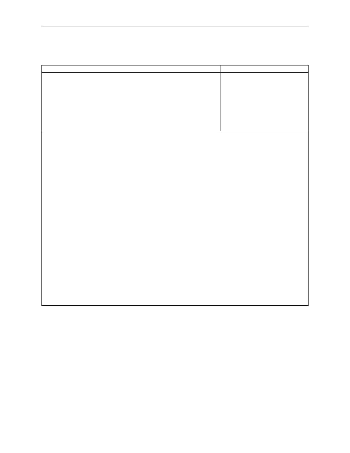
Table 17.1
Transformer insulation
Insulation required Type of insulation
1. Insulation between the primary wires of opposite polarity and between
secondary wires of opposite polarity having a potential greater than 30
volts rms (42.4 volts peak)
a,b,cord
2. Insulation between the primary and any secondary winding a, b, c or d
3. Insulation between any winding or lead connections and dead-metal
parts
a, b, c, d, e, f or g
4. Insulation between the crossover leads and (1) the turns of a different
winding, (2) the metal enclosure of a converter or inverter, or (3) the
core
a, d, e, g or h
a
Electrical grade paper that is waxed or otherwise treated to retard the absorption of moisture and that has a total thickness of
not less than 0.028 inch (0.71 mm); polyethylene terephthalate film, not less than 0.007 inch (0.178 mm) thick; or aramid paper,
not less than 0.0085 inch (0.203 mm) thick.
b
A thermoplastic or thermostat coil form not less than 0.028 inch thick.
c
A material having a thickness less than 0.028 inch may be used provided that it is equivalent to Note a or b and the material
has a minimum dielectric breakdown strength of 5000 volts for the thickness used when tested as specified in Testing on
Transformer Insulating Materials, Section 41.
d
Spacings specified in Table 17.2 may be used in place of the specified insulation.
Exception: Spacings in Table 28.2, if applicable, may be used.
e
Electrical grade paper, waxed or otherwise treated to resist the absorption of moisture, having a total thickness of not less
than 0.013 inch (0.33 mm) if used in conjunction with an air spacing of one-half that specified in Note d.
f
Electrical grade paper, waxed or otherwise treated to resist the absorption of moisture, having a total thickness of not less
than 0.028 inch if the insulation is in contact with the enclosure.
g
A material having a thickness less than that specified in Notes e and f may be used, provided that it is equivalent to Notes e
and f and the material has a minimum dielectric breakdown strength of 2500 volts for the thickness used for Note e and 5000
volts for the thickness used for Note f when tested as specified in Testing on Transformer Insulating Materials, Section 41.
h
Any type and thickness of insulation in addition to the magnet wire coating, or a through air spacing less than that specified in
Table 17.2 may be used between a crossover lead and the winding to which it is connected if the construction complies with
either of the following:
1. The coil withstands the appropriate dielectric voltage withstand potential described in 39.1 and 39.2. The potential is
to be applied between the coil leads with the crossover lead cut at the point where it enters the inner layer.
2. The coil withstands the induced potential described in 40.1 – 40.4.
DECEMBER 14, 1993 UL 458 33