3 OPERATION
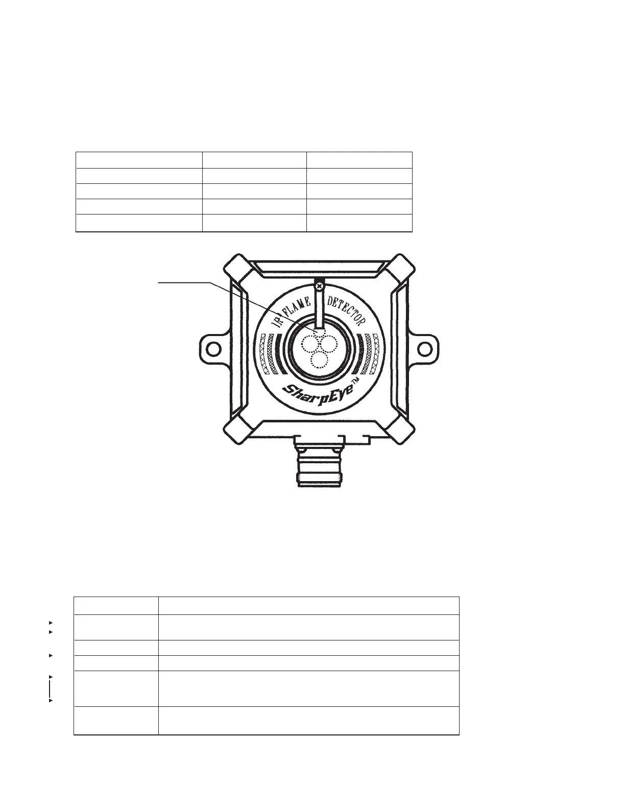
3.1 VISUAL INDICATIONS
One 3-color LED-indication is located in the detector front window:
FIGURE 4: INDICA
TION LEDS
3.2 OUTPUT SIGNALS
The detector controls the following outputs:
• Alarm relay
• Fault relay
The detector can be in one of the following states.
In each state, the detector will activate different outputs as specified in table 3-2.1.
O
PERATION
7
-1-07 Page 7
REV. 1
D
ETECTOR STATUS LED COLOR LED MODE
Fault, BIT Fault Yellow 4 Hz flashing
Normal Green 1 Hz flashing
Warning Red 2 Hz flashing
Alarm Red Steady
NORMAL: The detector is functioning normally.
MANUAL/
AUTOMATIC BIT: The detector performs a Built In Test.
WARNING: Fire detected – warming alarm (prealarm) state
ALARM: Fire detected – fire alarm state
MANUAL/
AUTOMATIC BIT
FAULT: A fault is detected during BIT sequence.
FAULT:
A fault is detected when the power supply is too low or during a software
fault.
STATUS LED
0
06851
 Loading...