3
Connecting the USB Ports
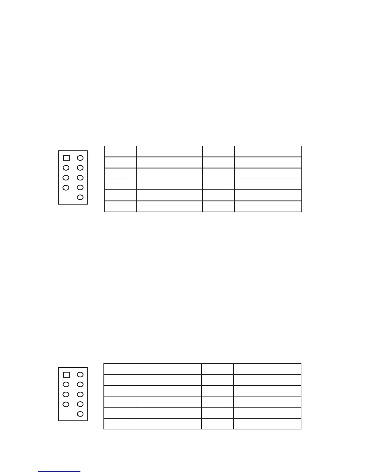
You will find a single 10-pin connector on a cable attached to the front USB ports.
This is an Intel standard connector, which is keyed so that it can’t be accidentally
reversed as long as it is connected to a proper Intel standard motherboard header.
Connect the 10-pin connector to your motherboard headers so that the blocked pin
fits over the missing header pin.
Note: Please check your motherboard manual for your USB header pin layout and
make sure it matches the attached table. If it does not match this Intel standard,
please call Antec customer support at (800) 22ANTEC (North America) or at
+31 (0) 10 462-2060 (Europe) to buy a USB adapter. This adapter will allow you
to connect the front USB to your motherboard on a pin-by-pin basis.
Motherboard Pin Layout
Connecting the IEEE 1394 (FireWire®, i.Link®) Port
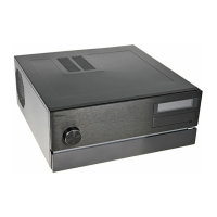
You will find a single 10-pin connector on a cable attached to the front IEEE 1394
connection. This is an Intel standard connector, which is keyed so that it can’t be
accidentally reversed as long as it is connected to a proper Intel standard mother-
board header. Connect the 10-pin connector to your motherboard header so that
the blocked pin fits over the missing header pin.
Note: Please check your motherboard manual for your IEEE 1394 header pin
layout and make sure it matches the attached table. If you intend to connect the
front FireWire port to an IEEE 1394 add-on card that comes with an external-type
IEEE1394 connector, please call Antec customer service at (800) 22ANTEC (North
America) or +31 (0) 10 462-2060 (Europe) to buy an adapter. This adapter will
allow you to connect the front IEEE 1394 port to the external-type connector.
Pin Assignment for Front Panel IEEE 1394 Connector
Pin Signal Names Pin Signal Names
1
USB Power 1
2
USB Power 2
3
Negative Signal 1
4
Negative Signal 2
5
Positive Signal 1
6
Positive Signal 2
7
Ground 1
8
Ground 2
9
Key (No Connection)
10
Empty Pin
12
10
9
Pin Signal Names Pin Signal Names
1 TPA+ 2 TPA–
3 Ground 4 Ground
5 TPB+ 6 TPB–
7 +12V (Fused) 8 +12V (Fused)
9 Key (No Pin) 10 Ground
12
109