Do you have a question about the Anviz T5 Pro and is the answer not in the manual?
Steps for drilling holes, fixing back panel, connecting cables, and securing the reader.
Diagram detailing the electrical connections for the access control reader.
Wiring diagram showing the connection between the reader and the power supply.
Wiring diagram illustrating the connection between the reader and the controller.
Diagram detailing the USB connection for PC communication.
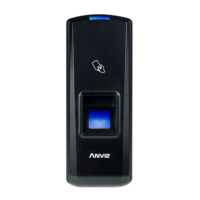
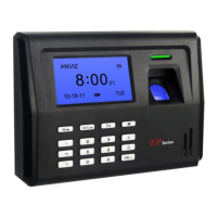
Description of LED colors (Red, Blue, Green) indicating device status.
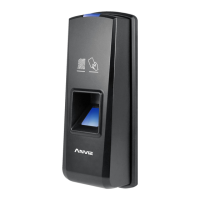
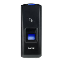
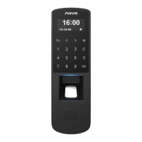
Identification of Card Reader Area, Fingerprint Sensor, and Screw Holes.
Guidance on placing the finger centrally and flatly on the sensor.
Examples of improper finger placement, including off-center or angled.
Steps for powering the device, indicated by blue LED and beeps.
Instructions for adding Fingerprint Only, Card Only, or Card+Fingerprint.
Procedures for deleting fingerprints or card+fingerprint combinations.
Action of the function button to clear registration data.
Process for registering management cards (Enroll and Delete Cards).
| Device Type | IP Access Controller |
|---|---|
| Access Control | Yes |
| Record Capacity | 100, 000 |
| Log Capacity | 100, 000 |
| Operating Temperature | -20°C to 60°C |
| Operating Humidity | 20% to 80% |
| Power Supply | 12V DC |
| Card Reader | EM |
| Communication | TCP/IP |
| Face Capacity | Not applicable |
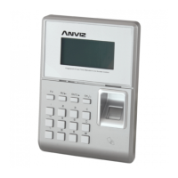
| Display | LCD |
| Dimensions | 40mm x 185mm x 60mm |
| Verification Speed | < 1 second |