This product contains parts that can be damaged by electrostatic discharge (ESD). Use
ESD prevention measures to avoid damage.
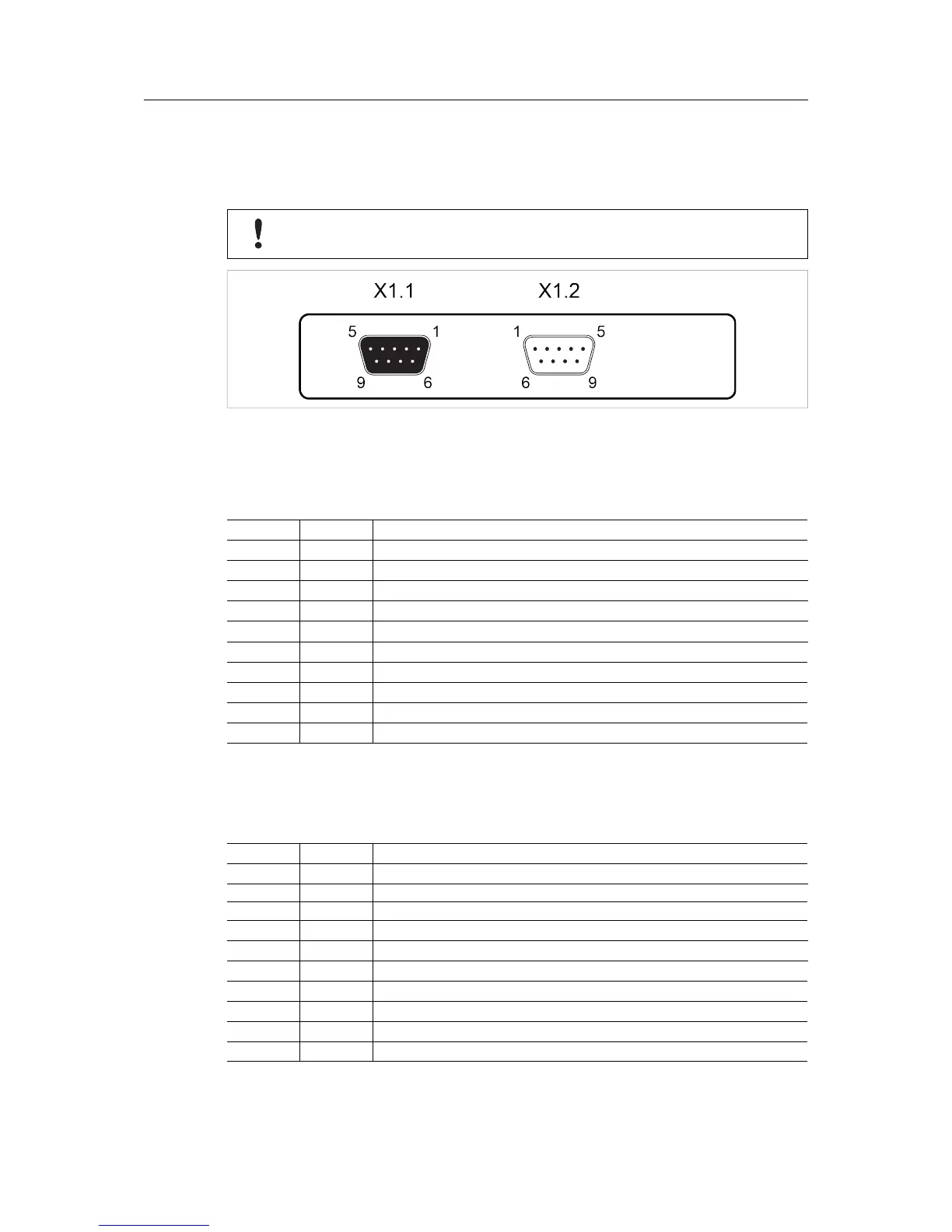
Fig. 2 PROFIBUS master adapter interface
PROFIBUS Connector X1.1 (female 9-pin D-sub)
If the node is the last on a bus segment, use a PROFIBUS connector with built-in terminating
resistors.
Pin
Signal
Description
1
-
(reserved)
2
-
(reserved)
3 Line B
Positive RS-485 RxD/TxD
4 RTS
Request To Send
5 GND BUS
Isolated signal ground (RS-485)
6 +5V BUS
+5 V (RS-485)
7
-
(reserved)
8 Line A
Negative RS-485 RxD/TxD
9
-
(reserved)
Housing
Shield Connected to PE
PROFIBUS Configuration Connector X1.2 (male 9-pin D-sub)
The PROFIBUS configuration connector is used to connect a computer to the master interface for
configuration. A null modem cable with female 9-pin D-sub connectors is required.
Pin
Signal
Description
1
-
(reserved)
2 RS-232 Rx
RS-232 receive data
3 RS-232 Tx
RS-232 transmit data
4
-
(reserved)
5 GND
Signal Ground
6 DSR
(reserved)
7
-
(reserved)
8
-
(reserved)
9
-
(reserved)
Housing
Shield Connected to PE
Anybus
®
X-gateway
™
PROFIBUS Master Interface Network Guide
SCM-1202-104 1.0 en-US
 Loading...