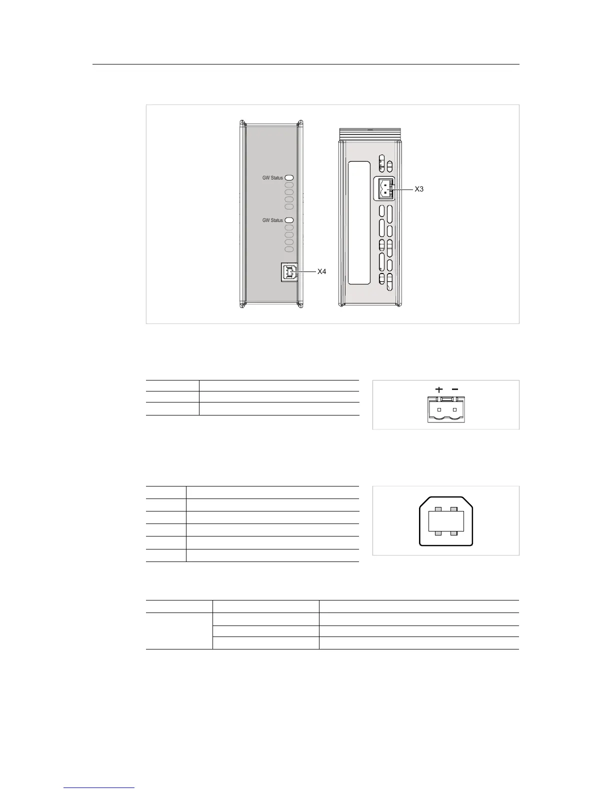
Fig. 9 USB type B connector
Pin Signal
1 +5 V input
2 USBDM (USB communication)
3 USBDP (USB communication)
4 Signal ground
Housing Cable shield
3.2.3 LED Indicators
LED Indication Meaning
GW Status Green Communication running
Red Communication error
Red, flashing Network interface error
All other LED indicators, connectors and configuration switches are specific for each network in-
terface and are described in the respective Network Guide.
Anybus
®
X-gateway
™
User Manual HMSI-27-262 3.0
 Loading...
