15
Table 16.3. Response frame format for the READ function (minimum frame length - 7 bytes):
address of
the device
function
4 or 3
data field (max. 40*2=80
bytes)
data field - register value CRC check sum
÷ 80
Example 16.3. Response frame for register value equal to 0: 0x01 - 0x04 - 0x02 - 0x0000 - 0xB930
Table 16.4. Response frame format for the WRITE function (frame length - 8 bytes):
copy of the claim frame for the WRITE function (Table 16.2)
Table 16.5. Special response (errors: function field = 0x84 or 0x83 in the case of the READ function and 0x86 in
the case of the WRITE function):
(HB-LB in the data field)
existing register address
wrong write register value
Example 16.5. Error frame for a non-existing read register address: 0x01 - 0x84 - 0x02 - 0x0001- 0x5130
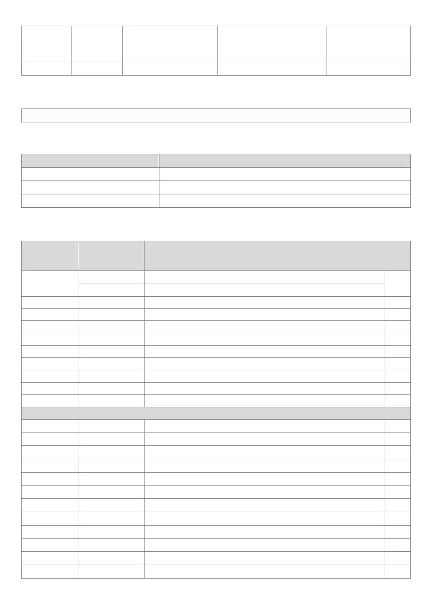
Table 16.6. Map of registers for the MODBUS-RTU protocol
Register
address
HEX (DEC)
Value
(HEX or DEC)
Description of register and access type
(R- read only register, R/W - read and write register)
0x00 (0)
-1999 ÷ 19999 current measurement value
R/W
-1999 ÷ 9999
value to be displayed for the remote input (when parameter 0: inP = rEMo)
0x01 (1) 517 device type identifier R
0x02 (2)
100 ÷ 999 meter software (firmware) version
R
0x03 ÷ 0x05 0 not used or reserved
R
0x06 (6) 0 ÷ 1 current alarm status: bit0, bit0=1 means that the alarm is on
R
0x07 (7) 0 ÷ 20000 current state of the analog output (0 ÷ 20000 μA or 0 ÷ 10000 mV)
R
0x08 (8)
-100 ÷ 700 thermocouple cold tip temperature (resolution 0.1°C )
R
0x09 (9) -1999 ÷ 19999 minimum measurement value
R
0x0A (10) -1999 ÷ 19999 maximum measurement value
R
0x0B ÷ 0x10 0 not used or reserved
R
Configuration parameters (chapter 10)
0x11 (17) 0 ÷ 17
parameter 0: inP type of measurement input (chapter 10)
R/W
0x12 (18) 1 ÷ 20
parameter 1: FiLt digital filtration of measurements (response time)
R/W
0x13 (19) 0 ÷ 3
parameter 2: dot position of the point or resolution for temperature
R/W
0x14 (20) -1999 ÷ 18000
parameter 3: Lo1 lower limit for the alarm or bottom of the indication range
R/W
0x15 (21) -1999 ÷ 18000
parameter 4: Hi1 upper limit for the alarm or top of the indication range
R/W
0x16 (22) 0 ÷ 4
parameter 5: out1 alarm type
R/W
0x17 (23) -1999 ÷ 18000
parameter 6: SEt1 preset value for the alarm
R/W
0x18 (24) 0 ÷ 9999
parameter 7: H1 alarm hysteresis
R/W
0x19 (25) 0 ÷ 1
Parameter 8: AtYP type of analog output
R/W
0x1A (26) 0 ÷ 3
parameter 9: outA function of analog output
R/W
0x1B (27) -1999 ÷ 18000
parameter 10: A-Lo lower indication for retransmission
R/W
0x1C (28) -1999 ÷ 18000
parameter 11: A-Hi upper indication for retransmission
R/W