6
b) AR518
144 x 72 x 72 mm (W x H x D)
IP54
grips on the side of the enclosure
cross-sections
2.5 mm
2
(power supply), 1.5 mm
2
(others)
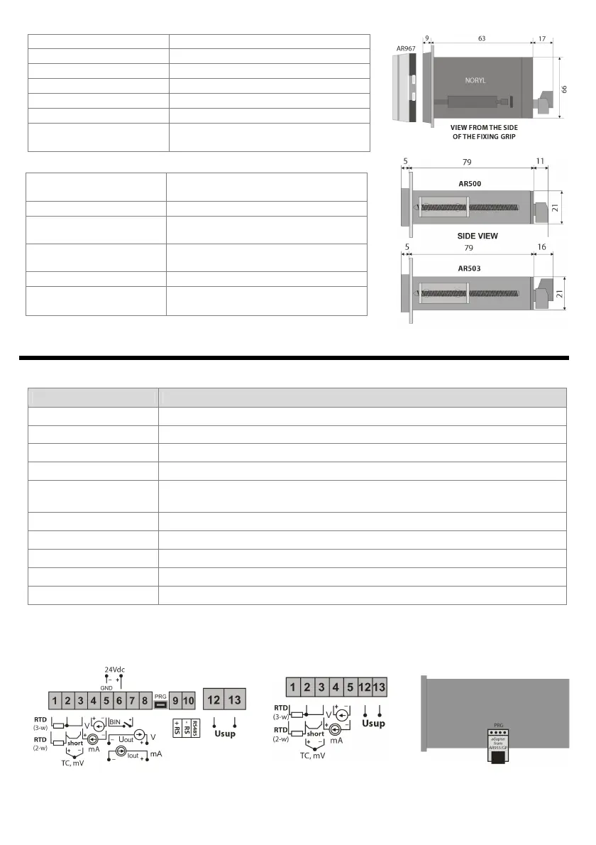
Table 7. Numbering and description of terminal strips
input Pt100, Ni100, Pt500, Pt1000, resistance, (2
thermocouple input TC (J, K, S, B, R, T, E, N) and voltage input 0÷60 mV
6 (none in the AR500)
output +24 V (in relation to the 5
GND) of the integrated power supply of field
transducers
binary input (contact or voltage <24 V)
analog current output (0/4÷20 mA) or voltage output
PRG
programming connection for cooperation with the programmer
RS485 serial interface (MODBUS
RTU transmission protocol)
power supply input 230 VAC or 24 VAC/DC (in AR500 only 24 VAC/DC)
a) numbering of the connections on the back panel, method of connecting sensors and measurement signals and
the PRG adapter in AR500 and AR503 (description of terminal clamps - Table 7)
a.1) in AR517, AR518, AR503 (PRG item a.3) a.2) in AR500 (PRG item a.3) a.3) AR500, AR503
(PRG adapter connected)
NOTE: For connecting the device with a computer through the PRG socket, use only the AR955 programmer (for
AR500 and AR503 with an optional adapter). A connection made with a regular USB cable may cause damage to
722408 (AR503)
72x24x79 mm (AR503)
68x22 mm (AR503)
grips on the side of the enclosure
cross-sections
2.5 mm
2
(power supply AR503),
1.5 mm
2
(others)
7. DESCRIPTION OF TERMINAL STRIPS AND ELECTRICAL CONNECTIONS