14
ARSOFT-WZ4
(free)
creation on the disk of a ready configuration file with a "cfg" extension
enabling programming the meter in the future using
the RS485 interface or the AR955 and ARSOFT-WZ1 programmer
- the program does not use communication with the meter
ARSOFT-WZ2
(payable)
display and recording of current measurement data from a maximum of 30 channels
at the same time (only from devices made by APAR)
- the program requires communication with the meter via the RS485 or PRG (AR955) port
The detailed descriptions of the aforementioned applications can be found in the installation folders.
NOTE:
!
Before establishing the connection, make sure that the MODBUS address of the device (parameter 19: Addr ) and
the speed of transmission (20: br ) are the same as the settings of the software. Moreover, in the software, set the
number of the COM serial port in use (in the case of the RS485 converter or the AR955 programmer it is the
number assigned by the operating system during installation of the drivers).
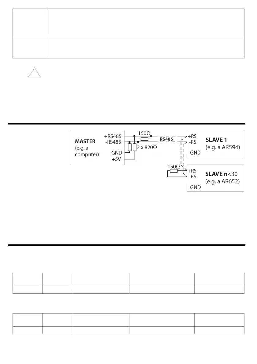
15. RS485 COMMUNICATION INTERFACE (acc. to EIA RS-485)
Max. RS485 cable length – 1 km. Max. no. of devices
in the RS485 line – 30 – in order to increase the number, use
RS485/RS485 amplifiers. Termination resistors when the MASTER
is at the start of the line (fig. above):
- at the start of the line – 2 x 820 Ω to the ground and +5 V MASTER and 150 Ω between the lines;
- at the end of the line – 150 Ω between the lines.
Termination resistors when the MASTER is in the middle of the line:
- at the converter – 2 x 820 Ω to the ground and +5 V converter;
- at both ends of the line – 150 Ω each between the lines.
16. MODBUS–RTU SERIAL TRANSMISSION PROTOCOL (SLAVE)
Character format: 8 bits, 1 stop bit, no parity bit
Available functions: READ - 3 or 4, WRITE - 6
Table 16.1. Claim frame format for the READ function (frame length - 8 bytes):
address of the
device
function
4 or 3
read register address:
0 ÷ 39 (0x0027)
number of read registers:
1 ÷ 40 (0x0028)
CRC check sum
1 byte 1 byte 2 bytes (HB-LB) 2 bytes (HB-LB) 2 bytes (LB-HB)
Example 16.1. Reading of a register with address 0: 0x01 - 0x04 - 0x0000 - 0x0001 - 0x31CA
Table 16.2. Claim frame format for the WRITE function (frame length - 8 bytes):
address of the
device
function 6
write register address:
0 ÷ 39 (0x0027)
write register value
CRC check sum
1 byte 1 byte 2 bytes (HB-LB) 2 bytes (HB-LB) 2 bytes (LB-HB)
Example 16.2. Entry in a register with address 10 (0xA) with the 0 value: 0x01 - 0x06 - 0x000A - 0x0000 - 0xA9C8