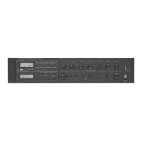
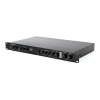
3. Rear Panel
16
15
18 19 20 32 31 28 29 30 27 33
17 21 22 24 24 25 25
26
26 27
23
28
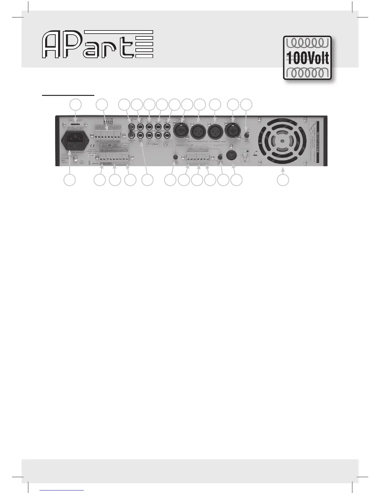
15) Voltage selector: Set the local voltage. If any doubt, contact your dealer. The unit is shipped with the selec-
tor set to 230VAC.
16) Mains socket: The unit can be connected to the mains circuit by a standard IEC type power cord. This socket
contains a 6,3AT, slow blow fuse. Use a screw driver to ip out the fuse compartment and to replace it by
the same type. When this fuse blows frequently, you should check the speaker load or bring the MA200 to a
qualied service centre. First check whether you didn’t use a quick-blow fuse!
17) Zone 100V loudspeaker outputs: When you need to activate/deactivate separate loudspeaker zones, you
should use these 100V outputs. These connectors should only be used for 100V operation. They are
activated by the selectors at the front (see 4). Don’t use these 100V outputs together with the 8 ohm, 50V
or 70V terminals. The minimum impedance of all 100V loudspeaker lines together should be at least 50Ω
(100Vx100V/50Ω = 200watt).
18) Emergency power supply: You can power the amplier directly from an emergency battery or power supply
supplying 24V DC/20A.
19) Loudspeaker outputs: For low impedance use com and 8Ω. Keep impedance above 8Ω.
For 50, 70 or 100V speaker lines use COM and 50, 70 or 100V terminals.
For 100V operation, the total minimum impedance of the loudspeaker lines should be 50 Ω. For 70V opera-
tion the minimum impedance should be 24,5 Ω and for 50V 12,5 Ω.
Don’t mix the types of speaker connections. Only one at the time should be used, unless you are able to
calculate a combination which does not overload the amplier (example: 100Ω at 100V for a loud zone in
combination with 25Ω at 50V for a quiet zone).
20) 24V DC output: At this terminal (-/+) 24V DC will be available (max. 1A) from the moment a priority has been
activated, to control priority relays of local volume attenuators or other devices.
21) Power amp in / pre amp out: You can send the signal of the pre-amplier to an external device such as an
equalizer (APart PXQ2215) or limiter and feed the treated signal back into the amplier via the power amp
input. From the “pre-amplier out” you can also feed extra power ampliers such as the Apart PA240P. Don’t
forget to feed the signal back into the “power amp in”. When you don’t use this feature, the RCA bridge
should be placed.
22) Tuner output mono: Here you can recover a xed signal of the internal tuner to feed other devices such as
your telephone’s ‘music on hold’ system.
23) Rec. out: When you need a copy of the total mix, you can connect this output to any recording device such
as tape deck, MD recorder, VHS recorder, etc….You can also use this output to feed an extra amplier. This
output level cannot be controlled separately. When you connect your MA200 pre amp out or record out to
a microphone input of another mixing amplier, this input will have signal overload and the sound will be
masked. In this case you should use a line input, a DI-box or other signal levelling device. Never connect
this output to an amplier loudspeaker output!