34001813EN/AE - Page 9
1. Presentation
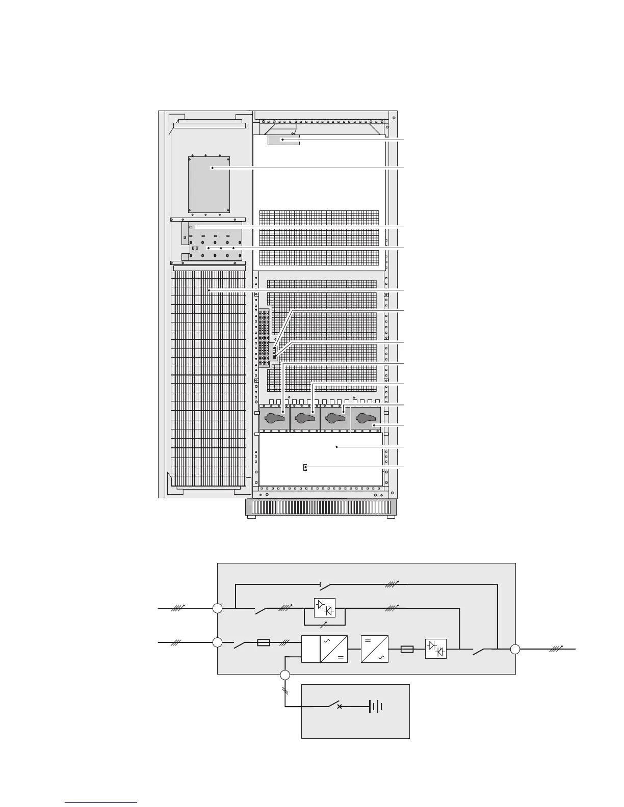
1.2 Inside the UPS cabinet, access to connections
Example of version with built-in battery
Simplified diagram of power connections
(1)Connectors for auxiliary interconnections
of parallel UPS units (INTN card)
(2)User-machine interface
(3)Slot for relay communications card
(4) Free slots for optional communication
cards
(5) Open cabinet door
(6) Screw-type terminal block for connections
of contacts and coils for two external battery
circuit breakers
(7) Screw-type terminal block for connection
of emergency power off (EPO)
(8) Q1: input switch for Normal AC input
(9) Q4S: input switch for Bypass AC input
(10) Q3BP: bypass switch
(11) Q5N: UPS output switch
(12) Protection cover for power-connection
terminal blocks
(13) QF1: battery circuit breaker (only
versions with built-in battery)
Q1 Q4S Q3BP Q5N
QF1
16
Q1
14
Q4S
Q5N
Normal AC
Bypass AC
15
FU
Q3BP
FU
PFC
QF1
22
Load
Battery cabinet