10
XL4 2nd Stage Maintenance Manual
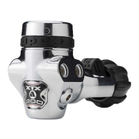
CAUTION: Ensure that the Diaphragm (6) and
Friction Ring (5) are seated correctly and are not
creased.
CAUTION:
Ensure that the
Lever (15) moves
freely and sits
vertically within
the case (13).
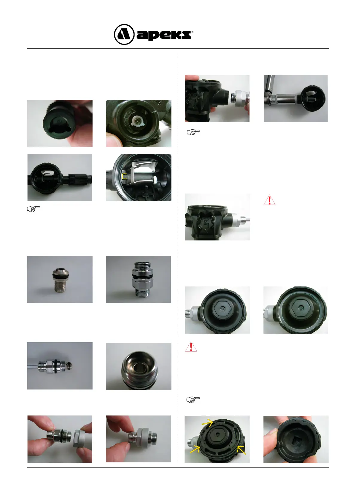
7. Using the opposite end of the Cracking Adjuster tool
(AT76) lined up with the Spindle Adjuster Sleeve (22) push
the Spindle Assembly rmly into the Case ensuring that
there is no gap between the two parts. Ensure that the
Lever has a full range of movement and does not catch on
the Valve Spindle Body.
NOTE: The square lug on the top side of the Spindle
Body (14) should engage into the slot in the Body (13).
8. Install a new Lubricated ‘O’ ring (17) onto the Valve Seat
(16) and O Ring (19) onto the Inlet Shrouded Fitting (20).
9. Carefully push the Valve Seat (16) into the larger diameter
bore of the Inlet Shrouded Fitting (20) threaded end rst.
Using a 5mm Hex Key (AT37) turn the valve seat counter
clockwise until it bottoms out.
10. Slide the Inlet Shroud (18) onto the Inlet Shroud Fitting
(20) hex side rst past the already installed O Ring.
11. Screw the Inlet Fitting assembly into the Spindle Body
(14) and torque to 3 Nm (2.2ft.lb) using a 13/16” socket.
NOTE: The 13/16” socket can be used on it’s own to
get a better grip when tting the Inlet Fitting assembly.
12. While holding the Case (13) at eye level, use a 5mm
Hex Key (AT37) to screw the Valve Seat (16) clockwise until
the Lever (15) drops just below the rim of the Case. Check
by gently icking the lever, it should bounce and have free
movement. The lever should return to its set position, if it
sticks then the lever is not square, tted incorrectly or it is
bent.
13. Ret the Diaphragm (6) into the front of the Case (13).
Using your nger carefully work the edges of the Diaphragm
into place so it sits evenly in the Case. Insert the Friction
Ring (5) into the case. Use the same technique to ensure it
sits evenly onto the Diaphragm.
14. Fit the Inner Locking Ring (4) ensuring the 3 small
grooves are facing up. (see pic below). Using the AT71 Tool
slowly screw the Inner Locking Ring into the Case. Hand
tighten only.
NOTE: Refer to section 7 on page 6 for Tool use
instructions.

 Loading...