Do you have a question about the Apeks TX50 and is the answer not in the manual?
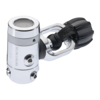
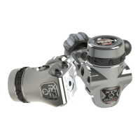
Details the flagship TX100 model's features including adjustable cracking control and satin chrome finish.
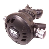
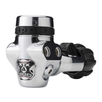
Outlines the TX50 model's features such as integrated venturi control and bright chrome finish.
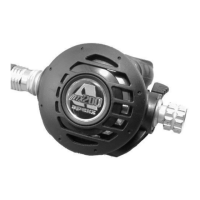
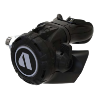
Lists the key features of the TX40 model, including pneumatically balanced valve design.
Describes the T20 model's features, emphasizing its integrated venturi control.
Provides safety warnings, cautions, notes, and details an official inspection checklist for the regulator.
Covers scheduled service intervals and general guidelines for performing regulator maintenance.
Explains standard terminology, conventions for part removal/installation, and acronyms used in the manual.
Details pre-disassembly checks, cautions, and the procedure for removing the hose.
Guides through the removal of the diaphragm, valve assembly, venturi lever, and related components.
Outlines steps for removing the shuttle valve, seat, exhaust tee, mouthpiece, and exhaust valve.
Instructions for fitting the exhaust valve, exhaust tee, diaphragm, and diaphragm cover.
Details the reassembly of the valve spindle, shuttle valve, springs, and counterbalance components.
Covers fitting the heat exchanger, adjusting the seat, and final checks for the valve lever.
Step-by-step guide for adding O-rings and screwing the hose onto the second stage regulator.
Instructions for fitting the comfo-bite mouthpiece and securing it with the clip.
Procedures for setting lever height, checking gas flow, and adjusting the seat for optimal performance.
Details how to perform an external leak test by submerging the regulator in water.
Explains how to conduct a subjective breathing test to assess regulator function and air delivery.
Guidelines for cleaning regulator components using an ultrasonic bath and appropriate solutions.
Information on lubricating O-rings and considerations for Nitrox compatibility.
Visual representation of the TX100 regulator components with part numbers.
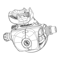
Visual representation of the TX50 regulator components with part numbers.
Visual representations of the TX40 and T20 regulator components with part numbers.
This document is a maintenance manual for the Apeks TX Second Stage Regulator range, intended for use by authorized technicians. It provides detailed procedures for the correct maintenance and repair of these diving regulators, ensuring their optimal performance and safety.
The Apeks TX Second Stage Regulator is a critical component of a diver's life support system, responsible for delivering breathable air to the diver at ambient pressure. The manual covers several models within the TX range, including the TX100, TX50, TX40, and T20, each offering a set of features designed to enhance the diving experience.
The primary function of the TX Second Stage Regulator is to reduce the intermediate pressure from the first stage regulator to a breathable ambient pressure, allowing the diver to inhale air comfortably underwater. It achieves this through a pneumatically balanced valve design, which minimizes breathing effort and ensures consistent air delivery regardless of depth or tank pressure.
Key components work in concert to achieve this function:
The Apeks TX Second Stage Regulators are designed for reliability and ease of use in various diving conditions, including cold water.
The manual emphasizes a structured approach to maintenance, ensuring the longevity and safe operation of the regulators. It is strictly for factory-authorized technicians who have completed an Apeks Service & Repair Seminar.
| LP Ports | 4 |
|---|---|
| HP Ports | 2 |
| Environmental Protection | Yes |
| Nitrox Compatibility | Yes, up to 40% O2 when new, beyond 40% requires special preparation |
| Ports | 4 LP ports, 2 HP ports |