12
TX Second Stage Regulator Maintenance Manual
13
TX Second Stage Regulator Maintenance Manual
FINAL TESTING
Setting the Lever Height
1. Connect the rst stage regulator to a calibrated test bench and
pressurise the system to 200 bar (±10) or 2900 psi (±145).
Connect an intermediate pressure gauge to the rst stage
regulator and ensure that the I.P. is set to 9.5 bar (±0.5) or
137 psi (±7.2). Make sure that the Adjuster Knob (28) is fully
wound out and that the Venturi Lever (14) is set to the “+”
position.
2. Tap the purge button quickly, this will cause the
regulator to freeow. Stop the freeow after a couple of
seconds by placing a hand over the mouthpiece.
3. Place the NO Gas Flow end of the TX Setting Tool (AT69
for all models except the TX100 or AT70 for the TX100)
onto the purge button decal (1). Depress the Purge button
by pushing the tool towards the 2nd stage until it stops
against the Front cover. If no gas ows from the second stage
proceed to step 5. If gas ows from the valve follow step 4.
4. Disconnect the second stage from the hose as shown in
step 1 of the disassembly procedure. Using the Slotted Seat
Adjuster Tool (PN AT51) , turn the seat (17) clockwise by
approximately 1/16 of a turn. Repeat step 3.
5. Place the Gas Flow end of the TX Setting Tool onto the purge
button decal (1). Depress the Purge button by pushing the
tool towards the 2nd stage until it stops against the Front
cover. If gas ows from the second stage the lever height has
been set correctly. If no gas ows from the valve proceed to
step 6.
6. Disconnect the second stage from the hose as shown in
step 1 of the disassembly procedure Using the Slotted Seat
Adjuster Tool (PN AT51) , turn the seat (17) anti-clockwise
by approximately 1/16 of a turn. Repeat both step 3 and step
5.
(Testing is continued on the next page)
Fitting Hose and Mouthpiece
WARNING: Ensure that the Mouthpiece is
properly secured on the outlet port.
NOTE: If your facility is equipped with a test bench,
perform the tests before installing the mouthpiece.
General instructions for performing bench tests are
located in the next section, “Final Testing.”
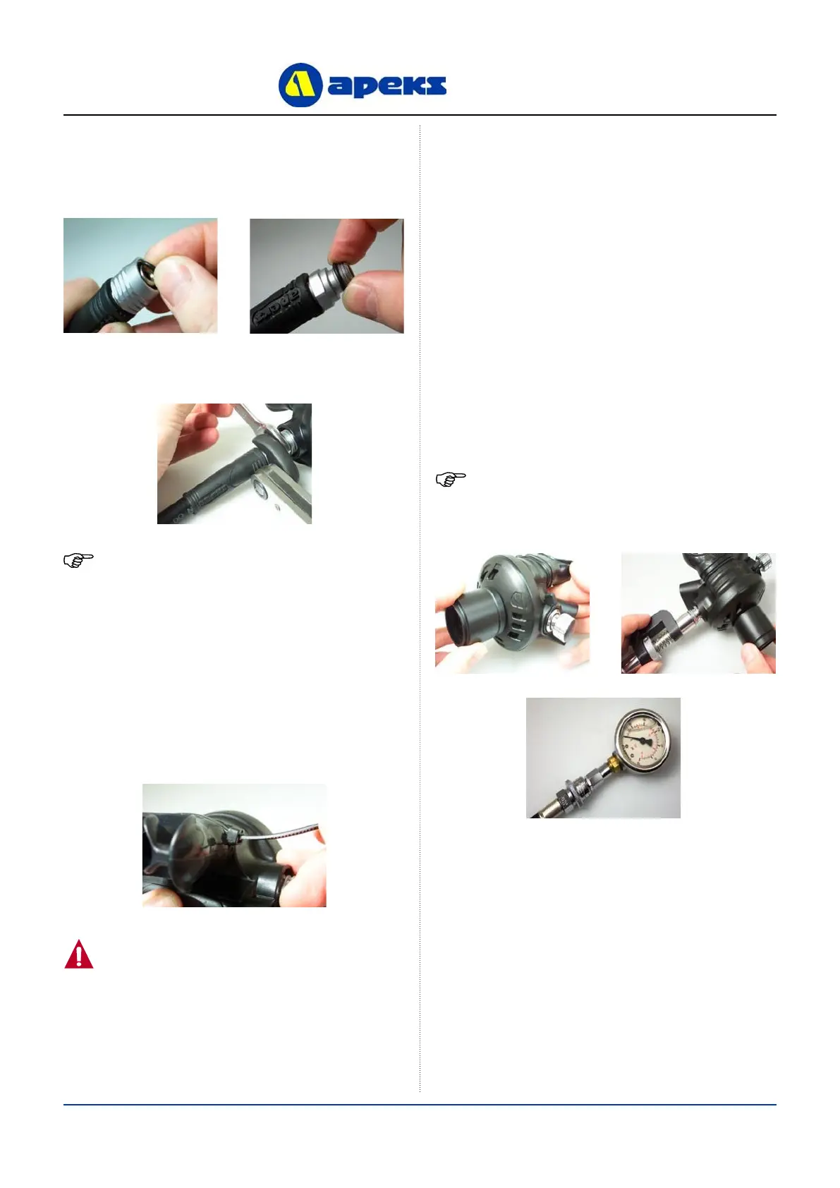
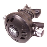
19. Screw the Hose onto the second stage. Using an 11/16”
crows-foot on a torque wrench and a spanner on the Heat
Exchanger, tighten the Hose to 5 Nm (3.7 lbf/ft).
18. Add a new ‘O’ ring to the male end of the Hose. Install a
new, lubricated ‘O’ ring into the swivel end of the Hose.
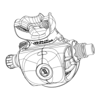
20. If equipped with a comfo-bite Mouthpiece, make sure the
‘bridge’of the Mouthpiece (12) is facing upward. Stretch
the Mouthpiece over the second-stage Mouthpiece outlet
port. At the base of the Mouthpiece is a groove for the
Mouthpiece Clip (11). Wrap the Clip around the Mouthpiece
so that the buckle points toward the Hose. Tighten the Clip
and snip the excess with side cutters.
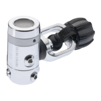
NOTE: An inline adjuster can be used can be used as
shown below. This allows the seat (17) to be adjusted
without having to disconnect the second stage from the
hose.