14
XTX Second Stage Regulator Maintenance Manual
6. Disconnect the second stage from the hose as shown
in step 1 of the disassembly procedure. Using the
Slotted Seat Adjuster Tool (PN AT51) ,turn the seat
(15) anti- clockwise by approximately 1/16 of a turn
(see step 14 of reassembly procedures for Ref.
Repeat both step 3 and step 5. As a nal check now
tap the purge button as in Step 2 causing freeow,
stopping this by placing hand over mouthpiece.
Second Stage Opening Effort Test
1. Connect the rst stage regulator to a calibrated test
bench and pressurise the system to 200 (±10) bar.
Slowly open the owmeter control knob (start vacuum)
while watching both the magnahelic gauge and the
intermediate pressure gauge.
2. When the intermediate pressure begins to drop,
indicating the second-stage valve is open, the
magnahelic gauge should indicate an opening effort
of +1.0 in.H
2
O (2.5mbar) to +1.5 in.H
2
O (3.7mbar). If
the reading is outside of these specications, adjust
the micro Adjuster (38), turning anti-clockwise to lower
the opening effort or clockwise to increase the opening
effort. If this fails to give the correct reading refer to
“Table 1 - Troubleshooting” for corrective actions.
External Leak Test
1. After disconnecting the regulator from the ow bench,
connect it to a gas cylinder lled to approximately 200
bar. Open the cylinder valve to repressurise the regu-
lator, and submerge the entire system in a test tank of
clean water.
2. Observe any bubbles arising from the submerged
regulator over a one minute period. The
recommended time is necessary due to slower bubble
formation that occurs in smaller leaks. Bubbles
indicate a leak, which requires the system to be
disassembled at the source to check sealing surfaces,
assembly sequence and component positioning in
order to correct the problem(s).
NOTE: Extremely small leaks may be better
detected by applying a soap solution or Snoop™
to the leak area. Bubble streams will indicate the
source of the leak. Before disassembling to correct
any leaks, rinse the entire regulator thoroughly with
fresh water and blow out all residual moisture with
ltered, low-pressure air. Disassemble and remedy
the problem, referring to “Table 1 - Troubleshooting.”
Subjective Breathing Test
1. Depress the Purge Button fully to ensure that an
adequate volume of air needed to clear the second
stage ows through the mouthpiece. Then, inhale
slowly but deeply from the mouthpiece. A properly
serviced and adjusted regulator should deliver air upon
deep inhalation without excessive inhalation effort,
freeow, or “uttering” of the second-stage diaphragm.
When exhaling, there should be no uttering or
sticking of the exhalation valve. If any of these
problems occur, refer to “Table 1 - Troubleshooting”.
NOTE: If the Spindle Collar (17) is not correctly
positioned, the regulator will not freeow. The the
hole in the Valve Spindle (18) should also face the
top of the Case (24). Disassemble and remedy the
problem, referring to steps 7 to 9 of the reassembly
procedure.
FINAL TESTING
WARNING: Compressed air can be highly
explosive and is dangerous if misused. Ensure
cylinder valve is opened slowly. Use eye and ear
personal protective equipment when performing
any tests involving compressed air.
Setting the Lever Height
1. Connect the rst stage regulator to a calibrated test bench
and pressurise the system to 200 (±10) bar. Make sure
that the Adjuster Knob (35) is fully wound out and that the
Venturi Lever (13-14) is set to the “+” position.
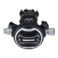
2. Place the NO GAS FLOW side
of the XTX Tool (PN AT20F)
onto the purge button. (1).
Depress the Purge button by
pushing the tool in until it stops
against the Front cover. If no
gas ows from the second
stage proceed to step 4. If gas
ows from the valve follow step
3.
3. Disconnect the second stage
from the hose as shown in step
1 of the disassembly procedure,
(excluding ‘O’ Ring removal).
Using the Slotted Seat Adjuster
Tool (PN AT51), turn the seat
(18) clockwise by approximately
1/16 of a turn (see step 16
of the disassembly procedure
for Ref.). This lowers the lever
inside. Repeat step 2.
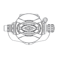
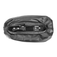
4. Place the GAS FLOW side of the
XTX Tool (above right) onto the
purge button(1) as positioned
before. Press the Purge in until it
stops against the Front cover. If
gas ows from the second stage
the lever height inside is correct.
However, if no gas ows from the
valve this means that the lever is
now set too low. Proceed to step
6.
5. Tap the purge button quickly, this should cause the regulator
to freeow. Stop the freeow after a couple of seconds by
placing a hand over the mouthpiece.
NOTE: It is important to ensure that the rim of the
tool is concentric with the rim of the purge button
throughout. Pressing on the logo with the tool mis-
aligned will not measure the purge button (depth of
pressing) and therefore, sensitivity, correctly.
This Ends Reassembly
NO GAS FLOW
GAS FLOW
 Loading...