APOGEE ELECTRONICS
11
AD-16X – User’s Guide
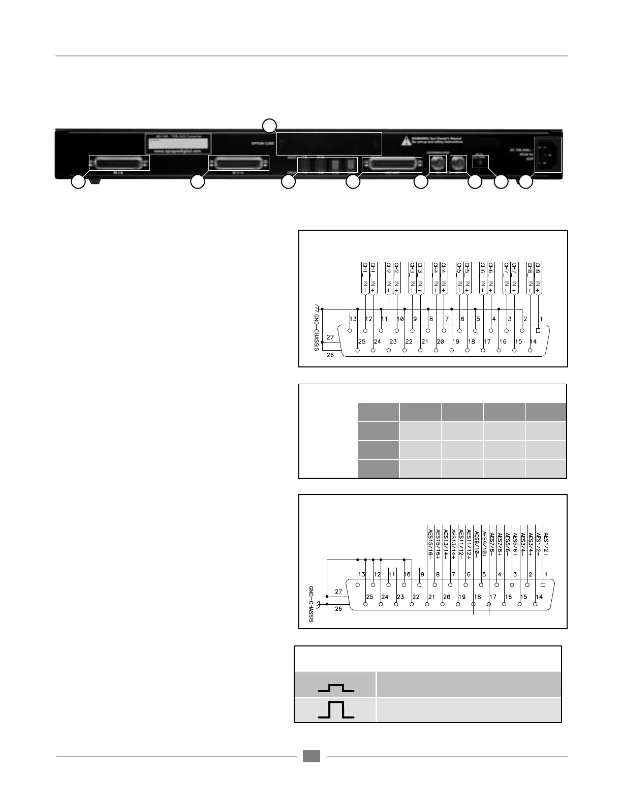
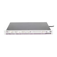
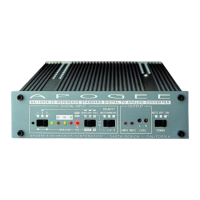
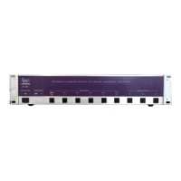
Connections on the Rear Panel
1) IN 1-8 - This DB-25 connection accepts analog
inputs 1-8; analog inputs are balanced line level
signals at a nominal level adjustable between
+4 dBu = -22 dBFs and -10 dBV = -10 dBFs.
Apogee’s AD8-IFC breakout cables can connect
here to provide 8 XLR female connecters. (pinout
Figure 3).
2) IN 9-16 - This DB-25 connection accepts analog
inputs 9-16. Apogee’s AD8-IFC breakout cables
can connect here to provide 8 XLR female con-
necters. (pinout Figure 3).
3) OPTION - This slot is reserved for Apogee’s X-Se-
ries Option cards, which provide additional digital
output formats, such as FireWire or Digidesign
HD.
4) ADAT – S/MUX These Toslink connections pro-
vide ADAT or S/MUX format optical outputs; the
format employed is based on the AD-16X sample
rate as indicated in Figure 4: also indicated are
the connections used for each format.
5) AES OUT – This DB-25 connector provides 16
channels of AES-EBU Single wire output and 8
channels of Double wire output (pinout Figure 5).
Apogee’s AES16-OP-IFC breakout cable can con-
nect here to provide 8 XLR male connectors.
6) WC IN - This BNC connection accepts a TTL
Logic clock signal. Termination of the word clock
input may be engaged with an internal switch;
please see “Internal Adjustments”.
7) WC OUT - This BNC connection provides a TTL
Logic clock signal output.
8) WC IN Termination Switch - When this switch is
pressed IN, a 75 ohm load is engaged across the
word clock input; when the switch is OUT, the word
clock input is unterminated (Figure 6).
9) AC - This IES connection accepts an AC input of
100 to 240 VAC at a frequency of 50 to 60 Hz.
Figure 3
Figure 4
Pinout Diagram for AES OUT 1-16
Pinout Diagram for Analog IN 1-8 and 9-16
1
2
4
5
3
6
7
Figure 5
9
8
WORD CLOCK IN, Termination Switch
Terminated switch position
Unterminated switch position
Figure 6
Rear Panel Optical Connectors
1 2 3 4
Optical
Format
44.1-48k
ADAT:
1-8 9-16 1-8 9-16
88.2-96k
S/MUX 2:
1-4 5-8 9-12 13-16
176.4-192k
S/MUX 4:
1-2 3-4 5-6 7-8